July 2015 
Battery Managing Vehicle Control Unit.
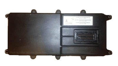
Since part of the battery electronics (BMS, contactors, current sensors and such) came integrated into the battery, this pretty much will dictate topology of the BMS system. Original Think EV BMS consisted of the main controller (Main Lithium Energy Controller or MLEC) and 16 Remote Lithium Energy Controllers (RLECs) - two integrated into each of 8 battery modules. I don't have the MLEC to look at, but there is no need - it is published what MLEC does and what its electrical interface looks like. That's enough to clone it, however I also need other functions of an EVCU not related to the battery. After a few iterations of initial BMS design it became clear that it makes sense to combine functions of both units in one piece of hardware - BMVCU (Battery Managing Vehicle Control Unit). It will take care of controlling power inverters, chargers, battery hardware (main, precharge and safety contactors) as well as J1772 comm and interlocks function. A single main vehicle controller will handle all of this. The photo in the right is an example - A123's main BMS controller, it is actually a prototype made by SLS 3D printing process. A BMVCU would look no different if similar enclosure is used, but once the PCB is designed, I plan to fit it in the place of original Audi VCU. Later on i will replace the photo on the right with it.
![]() Concept diagram of the BMVCU. Actual schematic will keep evolving
being prototyped and tested, but the block diagram is pretty much settled as shown here.
It is designed with high voltage (650...800 VDC, e.g. mostly racing EVs) application in
mind. Because most of the power periphery (contactors, relays) is controlled remotely via
CAN bus while few drivers are directly driven from the microcontroller (Microchip
PIC32MX795F512L), this presents flexibility of generic use as user can add any own
periphery to be controlled over CAN. Why this particular CPU was chosen? It happened to be
used by my software developing partner for very similar product, so most of the software
serving periphery was already written and debugged. The LCD, FRAM and SD card memory, the
CAN handling, GSM modem comm routines are all directly usable, so it was no brainer to take
advantage of that. It was no compromise of any sort - given selection from scratch, I could
as well arrive to the same or close type of controller chip.
Concept diagram of the BMVCU. Actual schematic will keep evolving
being prototyped and tested, but the block diagram is pretty much settled as shown here.
It is designed with high voltage (650...800 VDC, e.g. mostly racing EVs) application in
mind. Because most of the power periphery (contactors, relays) is controlled remotely via
CAN bus while few drivers are directly driven from the microcontroller (Microchip
PIC32MX795F512L), this presents flexibility of generic use as user can add any own
periphery to be controlled over CAN. Why this particular CPU was chosen? It happened to be
used by my software developing partner for very similar product, so most of the software
serving periphery was already written and debugged. The LCD, FRAM and SD card memory, the
CAN handling, GSM modem comm routines are all directly usable, so it was no brainer to take
advantage of that. It was no compromise of any sort - given selection from scratch, I could
as well arrive to the same or close type of controller chip.
This page will get updated as the work on the BMVCU progresses. Most of its design can be defined after access to RLECs is worked, so that is where I will focus first.
So, next we will take closer look at the RLEC design, but before we get to the level of individual bits I wanted to present my methods and workflow of designing electronics in general, including BMVCU as an example in particular. This may be of interest to not yet very experienced designers and tinkerers who might find and adopt some useful techniques, tools and habits proven to be effective. At least they work for me.
Next - how to build all this stuff that works