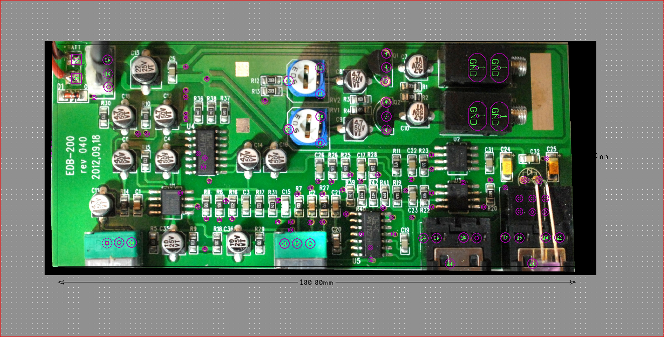
After taking high enough resolution photo of the preamp the image is imported into the PCB design software. The pads and traces are placed on the PCB overlaying the image that serves as as visual aid.
This page is more for people who are into electronics rather than musicians, but one does not exclude the other (like in my case).
I wanted to document how the internal preamp is built and if I can improve it or at least have a backup plan in case it will fail how to fix it or just build identical another one from scratch. For that a simple reverse engineering process allowed me to reconstruct electrical schematic of the preamp from the photo of the PCB (printer circuit board). I use CIRCAD software especially suitable for this kind of work. Without going into too much details of the process, below are a few snap shots of the work in progress and at the end - the reconstructed schematic of the preamp circuit. As you can see below, my actual model happened to be the EDB-200 rev 040, manufactured on Sept. 18 2012. My guess is Stagg continuously improves the design so the preamp you may have in your instrument may well have different revision and manufacturing date. However, the EDB-200 should give you general idea of what's inside these instruments and how it works.
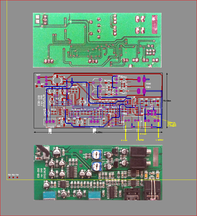
Below is the process of tracing the PCB and reconstructing the electrical schematic pretty much from the photographs of the PCB.
After taking high enough resolution photo of the preamp the image is imported into the PCB
design software. The pads and traces are placed on the PCB overlaying the image that
serves as as visual aid.
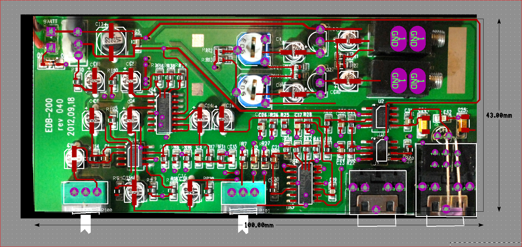
The copper traces are drawn as well matching those on the photo.
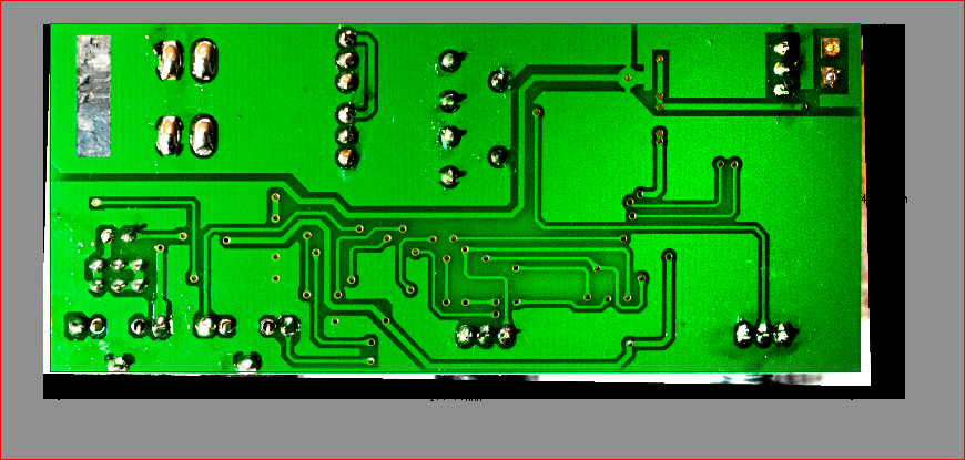
Back side of the board.
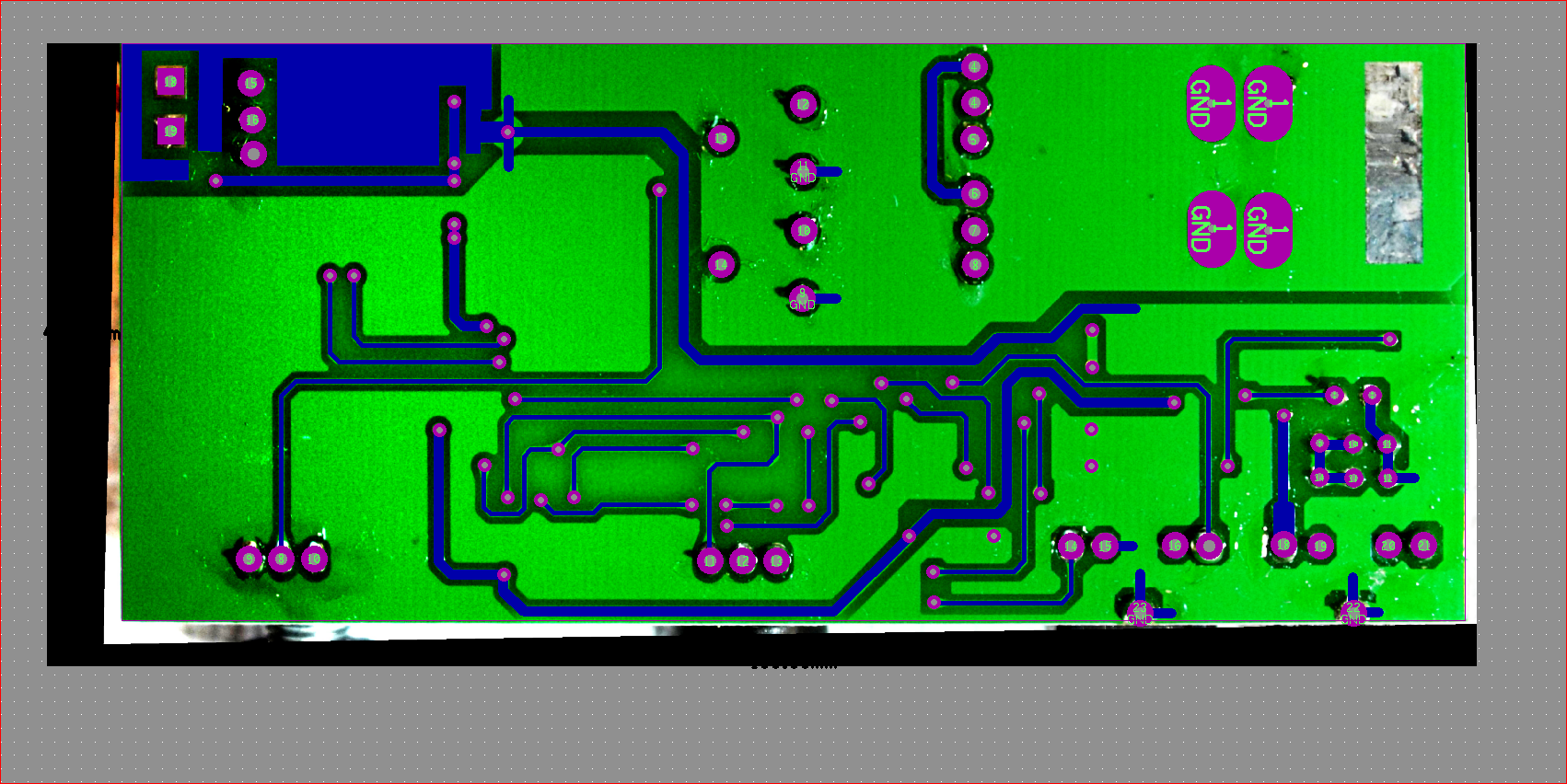
Same process - back side is traced and traces are drawn over the image.
Once that's done, the images are removed, leaving the PCB as if it's designed from
scratch.
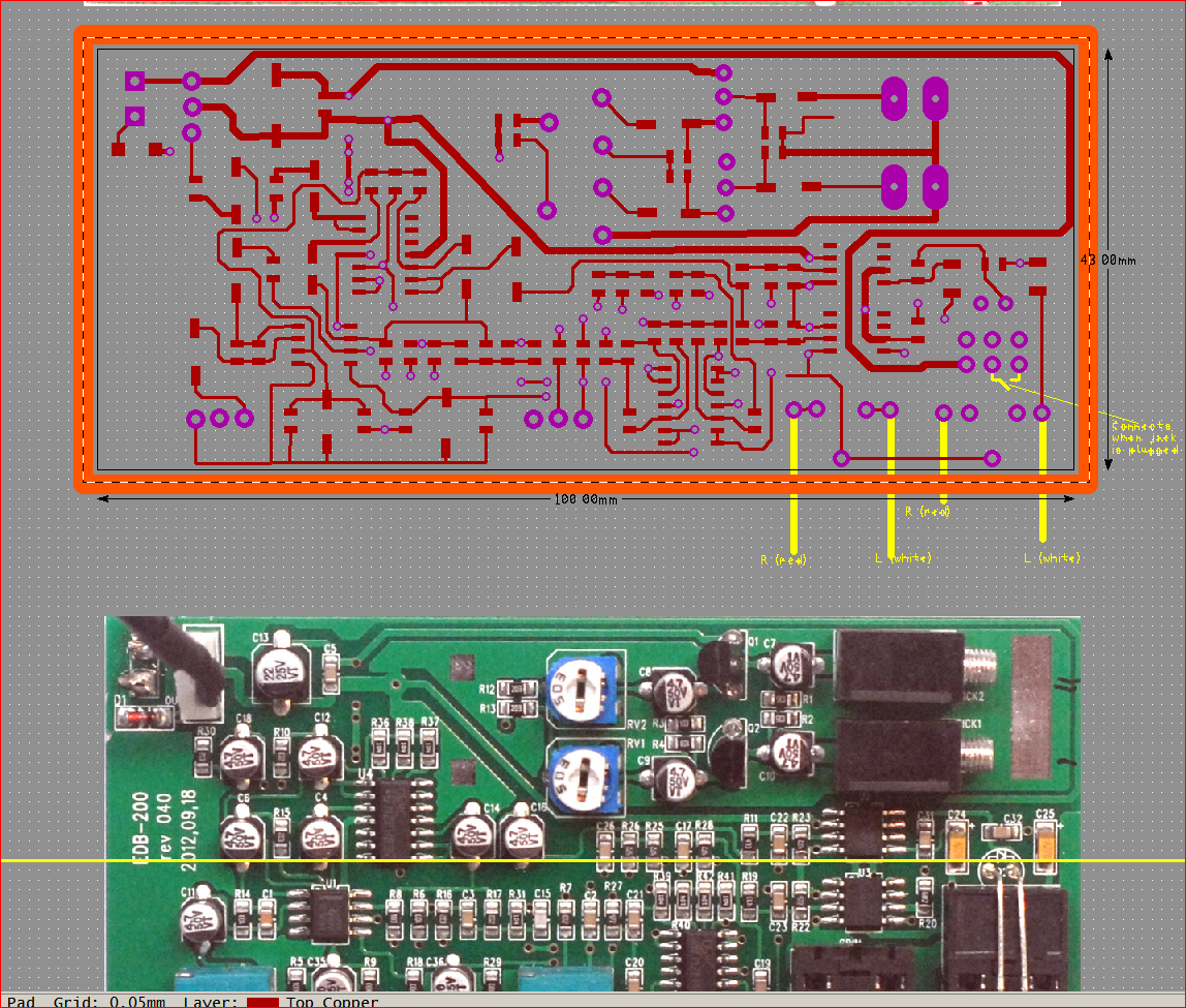
Now, the copper pour to top and bottom copper layers has to be applied to match actual
board construction.
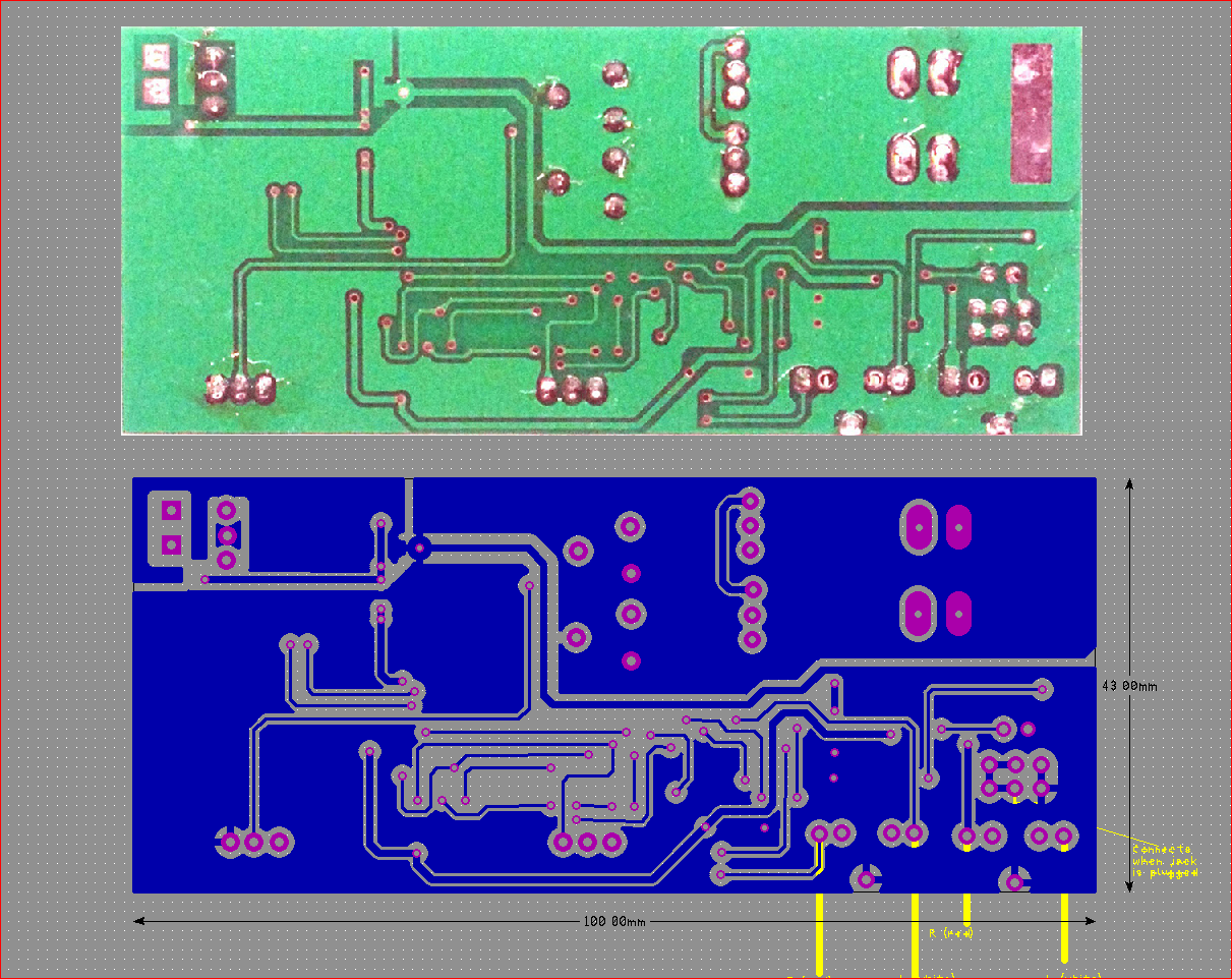
Bottom layer with copper pour. Now it matches what's on the photo above.
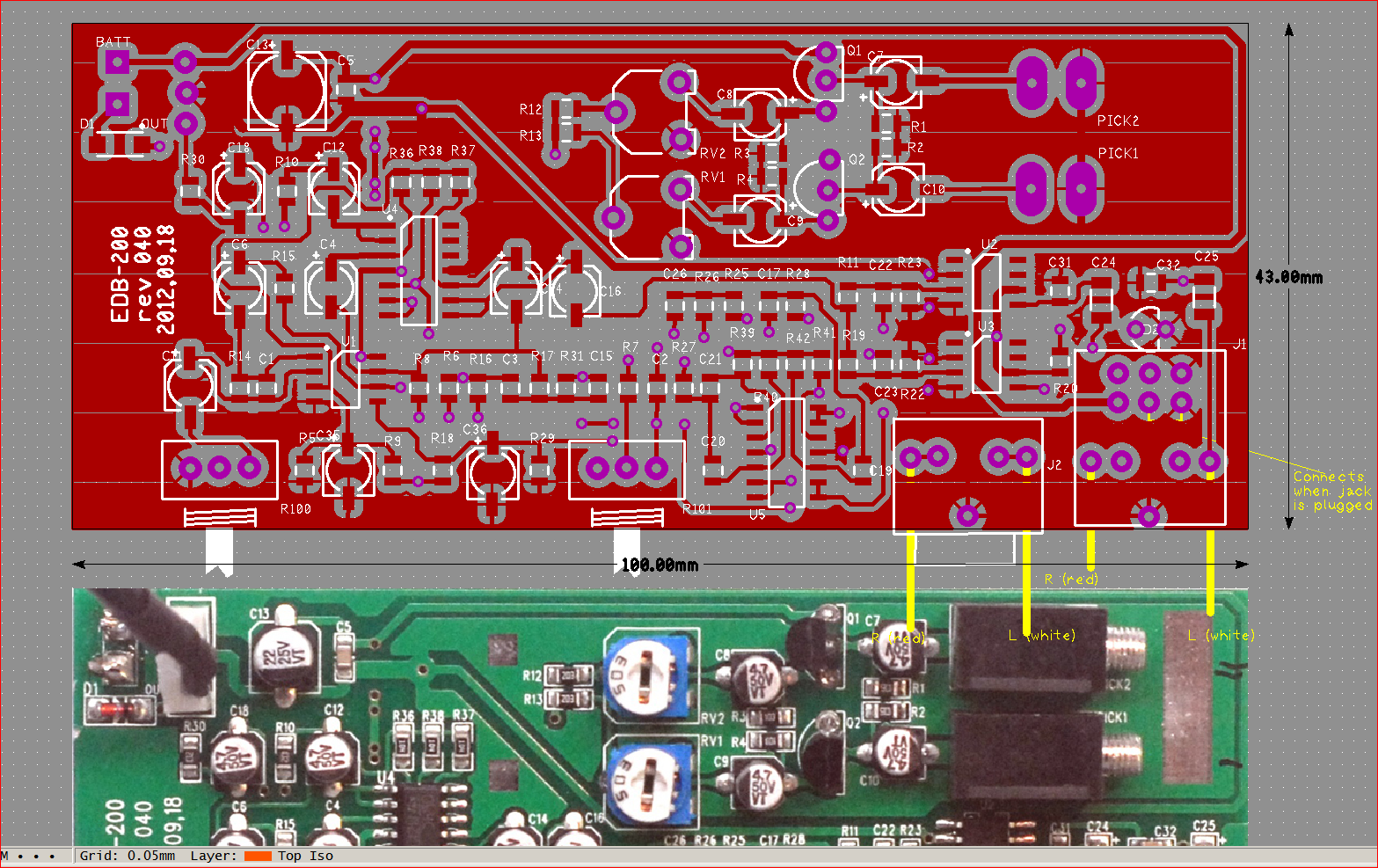
Same for the top layer - copper is poured.
Now, since the electrical connections between components placed on board from the library
are established, the cad can generate what's called a netlist - basically a list
describing where each pin of each component is connected to. Normally the netlist is
generated from an electrical schematic in order to link using copper traces all the pins
of physical components placed on the board from the cad library according to the netlist.
However, the process is symmetrical and if a netlist can be generated from the known
connections between components, once it is imported into the schematic capture part of the
cad software, interconnects between symbols representing components can also be
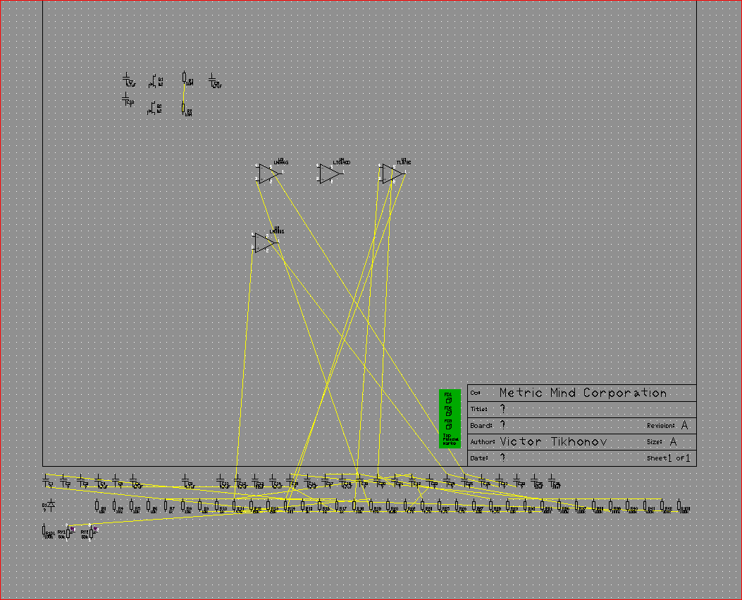
established and visualized as seen on this capture. Initially cad places all the symbols
it finds in the netlist along the bottom of the drawing sheet and uses yellow lines called
ratsnest to show all the electrical connections.
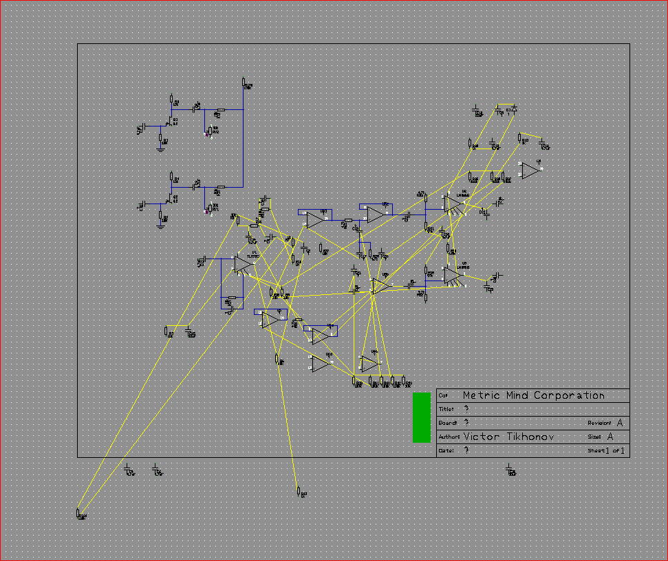
The symbols then are dragged one by one onto the drawing sheet and wires following
ratsnest lines are drawn neatly, per established practice (with very few exceptions all
the wire lines are either horizontal or vertical, junction dots placed, etc). From the
experience, I know what op amp based circuits normally look like, where bypass and filter
capacitors are placed, etc.
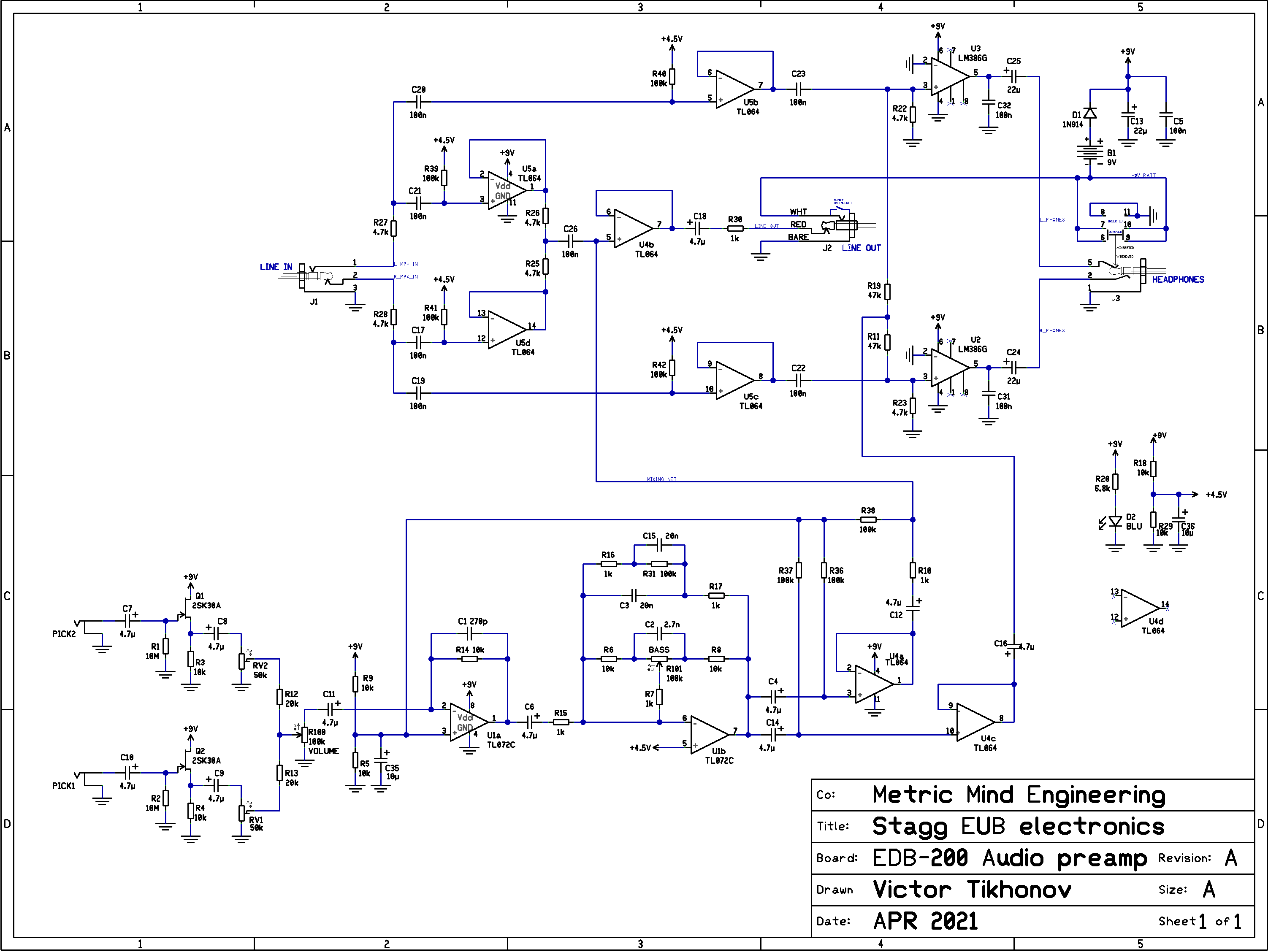
After some time spent dragging symbols around and establishing interconnects what emerges
is shown here. Click to enlarge, or you can download
Stagg EUB preamp schematic in .PDF format if you
prefer. Since I've traced the schematic and layout of the preamp PCB, I can now
repair it if it ever fails. Or if it comes to that, just built a new (or improved)
copy of the original. For now, though, I see no need to improve anything as it works
very well as designed, and I'm very satisfied with how my Stagg sounds with new strings.
Check out a couple of the recorded audio samples referenced on the introduction page, so you can judge how close the sound resembles acoustic upright bass. It is not possible to replicate the sound of acoustic bass since it is produced by vibrating wooden deck of the hollow bass body - something Stagg EUB just does not have. But reproducing acoustic upright was never the goal. It sounds like a real bass to other musicians and to the audience, so I'm very satisfied with it.
Good luck with your endeavors!
September 2022.
![]()