 Active Probe for an
oscilloscope
Active Probe for an
oscilloscopeActive Probe for an
oscilloscope
Now and then I have to check out sensitive circuit which cannot tolerate input impedance of a standard scope probe even if set to 100:1 attenuation. Any probe loads the circuit under test with a few pF of probe's input capacitance. CMOS based crystal stabilized clock oscillators are one type of such circuits - connecting extra 5-6 pF directly to the crystal can easily stop oscillation. HF filters are one other class of such circuits - they will work but will immediately get out of tune as soon as loaded with such scope probe. Anyway, there is good reason active probes, single ended or differential, exist. You can find quite a few commercial probes as well as private projects of inclined individuals designing their own ones.
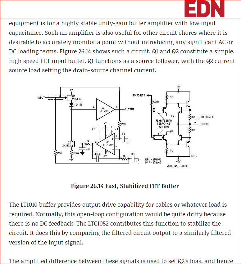
Full credit for the probe design presented here goes to the brilliant engineer I admire - Jim Williams, who published it in 2011 in one of his app notes while working at Linear Technology Corp. There are two flavors of the gadget he proposed: one with lower bandwidth using single buffer IC, and another using discrete components, which thus is more complicated to put together, but should have better performance (mainly - bandwidth) - that's the one I chose to replicate. It may not make much sense to construct a probe far exceeding bandwidth of the scope it will be used with, however as this is an investment of time and effort - if I ever consider upgrading my lab scope(s), I wouldn't want probes to become bandwidth limiting bottleneck.
The only difference between published original design and my implementation is substitute of a few obsolete transistors that are either no longer available or very hard to get. I've also added an isolated DC/DC converter (per probe) running off of the scope's 5V USB power to power it.
I've designed two versions of the PCB for the probe - with components mounted on one side and on both sides. Latter one appears more "symmetrical" and compact, so I've settled on that. The probe's tip is made from a spring loaded test pogo pin, which is inserted through the hole drilled from the side of the PCB and soldered to a barrel formed by large through hole. To make drilling easier and increase rigidity of the probe, the chosen thickness of the PCB material is 1.93mm. The tip diameter is 0.65mm.
Here is the schematic of the probe in CIRCAD format. For those of you who have never heard of CIRCAD (too bad...), here is
PDF version of it.Likewise, here is the PCB layout of the probe in native CIRCAD format. Most likely you don't use this terrific but no longer supported software (though you still can get it), so welcome to import Gerbers uploaded here and redraw the layout in the software of your choice if you wnat to modify it.
Probe performance.
Below are few screen captures depicting test results. I was delighted to witness the probe starting working right away. Tested from the scope's calibrator 1 kHz rechtangular wave output, I've observed about 3.6ns delay in rise time for leading edge of the pulse and 3.9ns for the trailing edge. The test pulse does not have exceptionally fast rise and fall times, they jsut has to correspond to a frequency exceeding at least 2X...3X scope's bandwidth (200 MHz in my case). However, my only concern was whether the probe's output pulse slopes not following the input, which would imply limited bandwidth. if a perfectly shaped pulse is just delayed, that would be fine. The good news was that the probe's output pretty much followed the rate of changes on the input. In other words, the bandwidth of the probe is exceeding the bandwidth of the scope itself, therefore the probe's exact cutoff frequency no longer matters. My guess is it exceeds 500MHz. I can confirm Jim's assertion that with 10 MOhm input resistance and <1pF capacitance the probe that cost me ~$50, performs the same function as >$1,000 commercial probes featuring the same functionality.
1 kHz calibrator signal. YLW trace - probe input, PNK trace - output.
A few screen grabs and photos below should
make the design and construction easier to grasp. A small brass tube (electrical ground) is placed
over the tip end of the PCB and partially covers the probe's tip. A braded strip soldered to the
tube is terminated with a microgrip clip. The probe PCB is completely encapsulated in clear heat
shrinked tube. The output coax cable and three power feed wires are plaed inside the thinner
heat shrink tube extending toward the BNC connector, forming a combined signal/power cable.
The DC/DC converter is mounted on the far end of the cable. Schematic: Mid layer 1: You can email me![]() Rising edge:
Rising edge: ![]() Falling edge:
Falling edge: ![]() Rising edge measured:
Rising edge measured: ![]() Falling edge measured:
Falling edge measured: ![]()
![]() Composite layout view:
Composite layout view: ![]() Top layer:
Top layer: ![]() Bottom layer:
Bottom layer: ![]()
![]() Mid layer 2:
Mid layer 2: ![]() 3D rendering:
3D rendering: ![]() Complete probe:
Complete probe: ![]() Probe tip:
Probe tip: ![]()

Old fashion email