How to make better falling plates pinhole camera
|
Micro-disclaimer: this
site consists of a single webpage coded by hand using old school HTML and yes, my own
human intelligence.
All thumbnail photos on this page are clickable links to actual size photos. Works just
fine. I've deliberately made vintage appearance
of the site created by vintage web page coding language match vintage appearance of photos
this pinhole camera takes.
I think all the info below illustrates everything one would want to know about how my
camera was built and how it works.
There are no downloadable CAD drawings or detailed instructions how to make one as
everyone's wish list is different,
it just visualizes some ideas that popped into my head while I was conceiving the design.
Welcome to replicate any of
it if you like what you see, and welcome to give me a feedback what I could have done better.
 This project is my third attempt to build a
more sophisticated pinhole camera. Photography has always had special place in my heart,
though I did not chose it as my profession. As a kid I watched my dad, professional
photograper, shooting rolls of film, conjuring in his dark room, handling his unobtainium
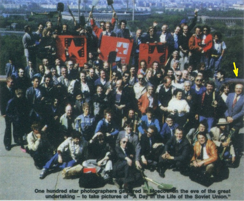
for plain mortals photo gear, and producing gorgeous world class photographs. Not only he
published few photo albums, he was ranked among 100 best photographers worldwide who were
chosen to participate in the "One Day In the life of the Soviet Union" 1987
project - capturing most interesting moments of life in technically no longer existing
country - former USSR, so I had someone who knew a thing or two about photography I could
learn from! Fast forward about 40 years, something sparked my interest capturing images
using the simplest camera one can imagine - a pinhole camera. 'Course, being tinkerer, I
naturally decided to make it myself.
This project is my third attempt to build a
more sophisticated pinhole camera. Photography has always had special place in my heart,
though I did not chose it as my profession. As a kid I watched my dad, professional
photograper, shooting rolls of film, conjuring in his dark room, handling his unobtainium
for plain mortals photo gear, and producing gorgeous world class photographs. Not only he
published few photo albums, he was ranked among 100 best photographers worldwide who were
chosen to participate in the "One Day In the life of the Soviet Union" 1987
project - capturing most interesting moments of life in technically no longer existing
country - former USSR, so I had someone who knew a thing or two about photography I could
learn from! Fast forward about 40 years, something sparked my interest capturing images
using the simplest camera one can imagine - a pinhole camera. 'Course, being tinkerer, I
naturally decided to make it myself.
After reading enough to get an idea what am I doing, I came up with a carton box with
the bottom of a soda can with a pinhole drilled in it, taped up front. The camera could be
loaded with a single 5"x7" B/W sheet photo paper serving as negative. The
positive image was created using contact print method.
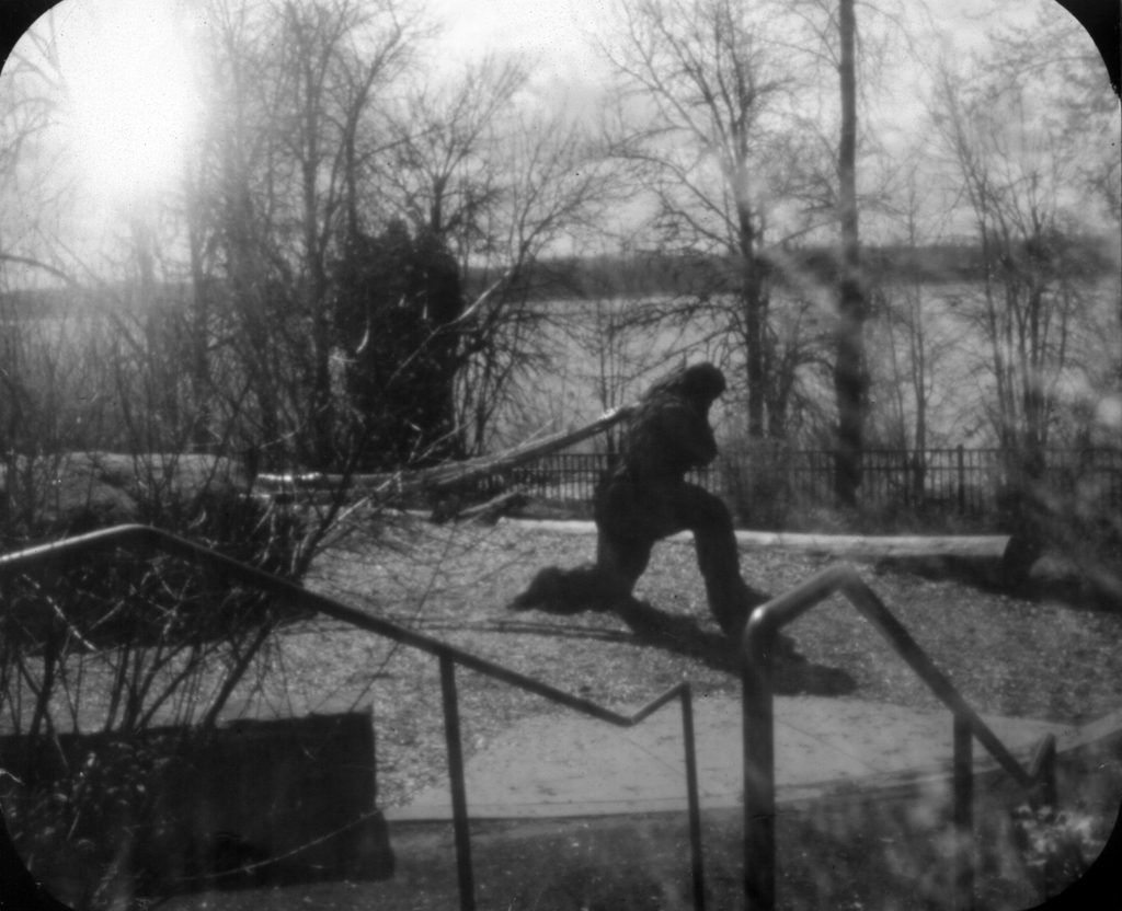
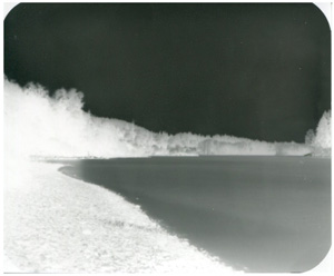
This worked, below is my very first photo made using this crude creation. It sported
something I don't think many pinhole cameras have - a viewfinder, consisting of just a
wire frame up front and an eyelet at the back to look through - one would get close to the
eyelet and the frame would approximately outline the confines of the scene that would fit
on the paper print. This worked reasonably well, but I wanted more. The main shortcoming
of this camera, aside from not very sophisticated view finder, was that it could take just
one shot before it had to be reloaded in the dark room. Also, 5"x7" photo paper
sheets, while inexpensive, were not very economical way to experiment.
So the second version described here was conceived. For multiple photos I saw a couple
of falling plates camera designs online, but they did not seem reliable - if the camera
was tilted backwards, the exposed plate might not fall down, so one should not only forget
to tilt it forward, but make sure the fallen plate did not move no matter how the camera
was handled. For instance, what happens with already fallen plates if the camera was
brought from place to place on its side and was set up upright again? Also, annoying
shortcoming was lack of the shots counter - there is no way to tell how many exposures
were taken. One would keep moving a slider alternating between two positions, but had to
manually keep track of how many photos are left to take.
I was determined to fix that. The camera I came up with has a clear indication which
sheet number is being exposed - this main distinction proved to be very convenient. Other
than that and the pinhole permanently covered by a yellow gelatin filter reducing
contrast, there is nothing very special about this camera's construction - may be
just a choice of material that has specific purpose and the back cover light trap design.
Read on.
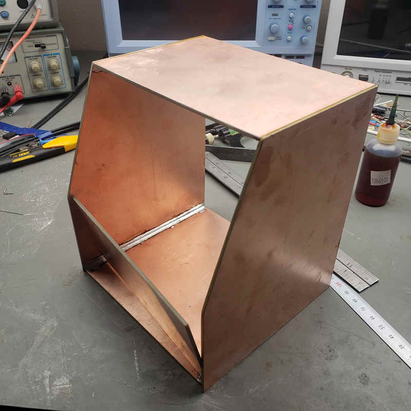 I did not want to build the camera using plywood - it would be quite a
bit bulkier than its inner size, and such material is not trivial to attach metal parts
to. Being electrical engineer by trade, my choice for the camera body material was clear -
clad laminated fiberglass sheets intended for fabrication of printed circuit boards.
Sturdy, light, easy to cut and drill, but the main advantage is having copper clad on both
sides, allowing body panels to simply be soldered together, as well as other inner parts
soldered to them. The body parts were made slightly oversized using measurement directly
on the screen, and then reduced to fit using belt sander and hand files. I ended up not
using the shape of the camera on this photo, but the concept and material remains.
I did not want to build the camera using plywood - it would be quite a
bit bulkier than its inner size, and such material is not trivial to attach metal parts
to. Being electrical engineer by trade, my choice for the camera body material was clear -
clad laminated fiberglass sheets intended for fabrication of printed circuit boards.
Sturdy, light, easy to cut and drill, but the main advantage is having copper clad on both
sides, allowing body panels to simply be soldered together, as well as other inner parts
soldered to them. The body parts were made slightly oversized using measurement directly
on the screen, and then reduced to fit using belt sander and hand files. I ended up not
using the shape of the camera on this photo, but the concept and material remains.
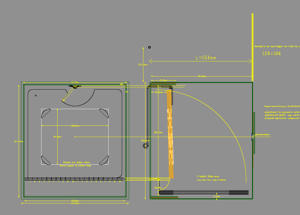 First, the camera design was visualized in CAD. Normally I build such
things with every next part tailored to physically fit to the previous part rather than
all parts made to predefined dimensions, no CAD drawings needed. But I needed to order the
main part of the camera - plates themselves to be laser cut, so the CAD files suitable for
uploading to the company providing sheet metal cutting service had to be created anyway.
First, the camera design was visualized in CAD. Normally I build such
things with every next part tailored to physically fit to the previous part rather than
all parts made to predefined dimensions, no CAD drawings needed. But I needed to order the
main part of the camera - plates themselves to be laser cut, so the CAD files suitable for
uploading to the company providing sheet metal cutting service had to be created anyway.
 Completed plates made of brass sheets as they came from metal cuters. I
chose to use 10 plates design for 10 exposures camera.
Completed plates made of brass sheets as they came from metal cuters. I
chose to use 10 plates design for 10 exposures camera.
 I've tried to make the pinhole in a piece of aluminum from a
soda can as well as in thinner foil - aluminum food tray. Aluminum is very dirty metal, it
is as soft as butter if parts are of microscopic dimensions. Poking a hole in it with the
tip of a needle always leaves torn uneven edges impossible to sand flat cleanly - I've
tried 600, 1000 and 2000 grit sandpaper. The hole always becomes clogged and if you try to
clean aluminum debris with the tip of a needle, you discover that the aluminum is so soft
that the shape of the hole after cleanup is no longer round. I never had much success
completely getting rid of any loose metal in the hole without making it irregular or
larger. Making a pinhole in the thinnest brass foil was a bit better, but not by much,
whether the hole was punched through or drilled with micro drill bit. Harder material had
to be used if I wanted good quality hole. I've decided to use stainless steel sheet metal,
and to have thinnest possible piece I bought a stainless steel Feeler gauge on Amazon. The
thinnest shim I cannibalized from it was 0.05mm (0.002") thick - half the thickness
of a typical aluminum soda can material. And it's far stronger, meaning easier to sand and
clean without affecting the hole shape.
I've tried to make the pinhole in a piece of aluminum from a
soda can as well as in thinner foil - aluminum food tray. Aluminum is very dirty metal, it
is as soft as butter if parts are of microscopic dimensions. Poking a hole in it with the
tip of a needle always leaves torn uneven edges impossible to sand flat cleanly - I've
tried 600, 1000 and 2000 grit sandpaper. The hole always becomes clogged and if you try to
clean aluminum debris with the tip of a needle, you discover that the aluminum is so soft
that the shape of the hole after cleanup is no longer round. I never had much success
completely getting rid of any loose metal in the hole without making it irregular or
larger. Making a pinhole in the thinnest brass foil was a bit better, but not by much,
whether the hole was punched through or drilled with micro drill bit. Harder material had
to be used if I wanted good quality hole. I've decided to use stainless steel sheet metal,
and to have thinnest possible piece I bought a stainless steel Feeler gauge on Amazon. The
thinnest shim I cannibalized from it was 0.05mm (0.002") thick - half the thickness
of a typical aluminum soda can material. And it's far stronger, meaning easier to sand and
clean without affecting the hole shape.
 I've used 0.4mm drill bit to drill the pinhole -
this is calculated optimal hole diameter for 122mm focal length. This screen capture show
the pinhole under microscope equipped with the video camera whose software allows precise
measurements. The hole appears very clean and actually 0.41mm, but the hole edges were
fuzzy to precisely place measurement grid and dimension lines, so I assume actual diameter
is somewhere in between. 0.01mm discrepancy wherever it comes from is negligible for the
purpose of calculating exposure.
I've used 0.4mm drill bit to drill the pinhole -
this is calculated optimal hole diameter for 122mm focal length. This screen capture show
the pinhole under microscope equipped with the video camera whose software allows precise
measurements. The hole appears very clean and actually 0.41mm, but the hole edges were
fuzzy to precisely place measurement grid and dimension lines, so I assume actual diameter
is somewhere in between. 0.01mm discrepancy wherever it comes from is negligible for the
purpose of calculating exposure.
The F-stop for my camera ended up to be 122/0.4=305. So the multiplier for the exposure
time measured by the lightmeter set to f=22 is (305/22)2=192. I should mention
that about 5x5 mm piece of yellow film filter, meant to recuce contrast of paper negatives
was taped over the pinhole plate on the inside, This filter was cut from theatrical stage
projector filter. It will slightly increases exposure time, so my optimal multiplier
after developing trial shots will likely ended up to be around 196...200. Actual pinhole
diameter will be taken into account for my tests, confirming that knowing exactly whether
pinhole itself ended up to be 0.40mm or 0.41mm is totally irrelevant.
 This particular set of plates is made for different version
of camera I ended up scrapping, but it illustrates the concept well. The long bent parts
were cut off and wrapped around common rod acting as a pivoting axle. The photo paper is
loaded by inserting 4 corners of each sheet into the cutouts in the plates. The top of
each plate has special cutouts shaped such that they form a staircase when stacked
together. The bent end of steel wire which protrudes through the back cover of the camera
initially holds entire stack of plates, and as I rotate the outside lever (basically a
steel wire hook), it slides along the "staircase" arch, releasing one plate at
the time. The plate no longer held by the hook then falls to the bottom of the camera.
This particular set of plates is made for different version
of camera I ended up scrapping, but it illustrates the concept well. The long bent parts
were cut off and wrapped around common rod acting as a pivoting axle. The photo paper is
loaded by inserting 4 corners of each sheet into the cutouts in the plates. The top of
each plate has special cutouts shaped such that they form a staircase when stacked
together. The bent end of steel wire which protrudes through the back cover of the camera
initially holds entire stack of plates, and as I rotate the outside lever (basically a
steel wire hook), it slides along the "staircase" arch, releasing one plate at
the time. The plate no longer held by the hook then falls to the bottom of the camera.
 What I just said above is far easier to illustrate on the
short video than explain - this video clip will make process of loading paper and
releasing the plates obvious. For this video I've used already developed paper as samples
to demonstrate how individual sheets are loaded and held in place. Obviously, all [up to]
10 sheets have to be loaded in the dark room under safe red light. 'Course fewer than 10
sheets can be loaded; likewise not all of them have to be exposed: once in a while I end
up making 6 or 7 photos at the time, so I just unload unused sheets in the dark room to be
used later.
What I just said above is far easier to illustrate on the
short video than explain - this video clip will make process of loading paper and
releasing the plates obvious. For this video I've used already developed paper as samples
to demonstrate how individual sheets are loaded and held in place. Obviously, all [up to]
10 sheets have to be loaded in the dark room under safe red light. 'Course fewer than 10
sheets can be loaded; likewise not all of them have to be exposed: once in a while I end
up making 6 or 7 photos at the time, so I just unload unused sheets in the dark room to be
used later.
 To get the best and most
economical use of photo paper I've decided on my custom format 100mm x 85mm (4" x
3.33") - this is exact dimensions of resulting sheets after cutting standard
8"x10" photo paper in 6 pieces with no waste. I normally buy a box of 25
8"x10" sheets, so end up with stack of 25*6= 150 small sheets for my camera.
Since I scan each negative sheet with 300dpi, the seemingly small size of negatives is
plenty large not only to have decent images on the computer screen, but print them out if
need be. Here is an example what it looks like.
To get the best and most
economical use of photo paper I've decided on my custom format 100mm x 85mm (4" x
3.33") - this is exact dimensions of resulting sheets after cutting standard
8"x10" photo paper in 6 pieces with no waste. I normally buy a box of 25
8"x10" sheets, so end up with stack of 25*6= 150 small sheets for my camera.
Since I scan each negative sheet with 300dpi, the seemingly small size of negatives is
plenty large not only to have decent images on the computer screen, but print them out if
need be. Here is an example what it looks like.
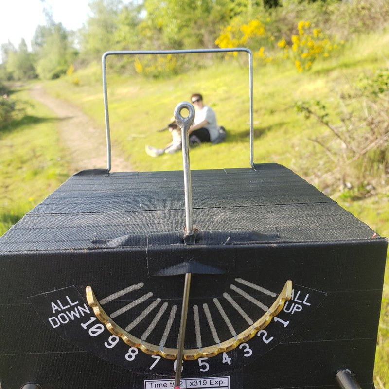 To aid in alignment with the subject, I came up with simple
view finder - just a wire frame with right dimensions distance and paper size, and the
"eye piece" - a simple wire with a loop at the end. This setup is calibrated
such that if I get my eye as close as practical to the eye piece to look through, the
scene within confines of the wire frame will fit onto photo paper. When not used, the wire
frame and the eye piece are folded down. The ends of wires on top of the camera are
pivoted inside a brass tubes soldered to the foil on fiberglass sheets the camera panels
are made of. Whole body is taped around with Gaffer's tape. You can also see two side
patches holding back panel firmly attached. The light seal is provided by rubber gasket
cut from a 3M 467MP porous black rubber sheet with one adhesive side, this works very
well.
To aid in alignment with the subject, I came up with simple
view finder - just a wire frame with right dimensions distance and paper size, and the
"eye piece" - a simple wire with a loop at the end. This setup is calibrated
such that if I get my eye as close as practical to the eye piece to look through, the
scene within confines of the wire frame will fit onto photo paper. When not used, the wire
frame and the eye piece are folded down. The ends of wires on top of the camera are
pivoted inside a brass tubes soldered to the foil on fiberglass sheets the camera panels
are made of. Whole body is taped around with Gaffer's tape. You can also see two side
patches holding back panel firmly attached. The light seal is provided by rubber gasket
cut from a 3M 467MP porous black rubber sheet with one adhesive side, this works very
well.
 To advance
to the next sheet a brass tiara with indents for the hook wire was designed. Indexing to
the next plate now has very distinct click, following with satisfying sound of next
falling plate shortly after. Each indent is marked with the sheet number being exposed, so
this visual counter proved to be very convenient and I believe is novel idea. Oh this
photo the brass tiara is shown from top, and also a drill bit used to drill blind holes
from the bottom of the tiara is shown along with wire pins soldered into these holes. I
drilled matching holes in the camera back, so the tiara could be inserted with pins
protruding through the back and soldered to the foil clad on the inside. Works like a
charm.
To advance
to the next sheet a brass tiara with indents for the hook wire was designed. Indexing to
the next plate now has very distinct click, following with satisfying sound of next
falling plate shortly after. Each indent is marked with the sheet number being exposed, so
this visual counter proved to be very convenient and I believe is novel idea. Oh this
photo the brass tiara is shown from top, and also a drill bit used to drill blind holes
from the bottom of the tiara is shown along with wire pins soldered into these holes. I
drilled matching holes in the camera back, so the tiara could be inserted with pins
protruding through the back and soldered to the foil clad on the inside. Works like a
charm.
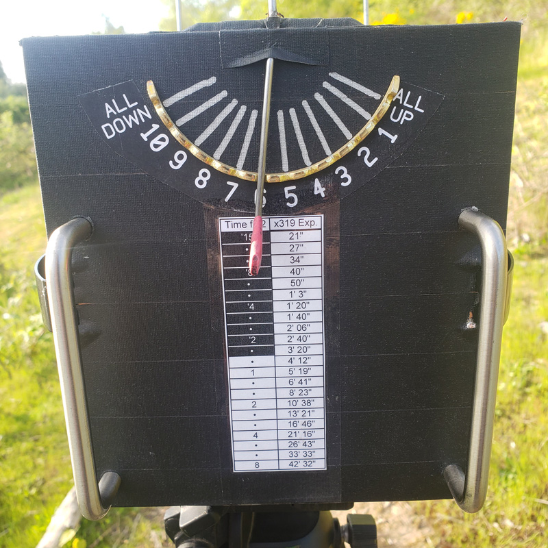 One detail on the back of my camera - a small table of practical exposure
times based on my Luna Pro light meter as the input. Left column replicates light meter's
times on the dial (including color coding of fractions of a second in black and whole
seconds in white) for the F=22, while on the right side - calculated corresponding
exposure times for the F=319 time multiplier. I've mentioned above that calculated
multiplier is about 200, but this photo was taken for the camera with pinhole of 0.32mm
diameter I've experimented with, not 0.4mm, so for smaller hole exposure time is
proportionally longer, so the multiplier was 319 instead of 200. My point though is that
no math exercise needed - so far all practical exposures I've ever encountered were well
within the limits min and max limits on this table. It is just a section of excel file
printed on paper which is taped to the back of the camera using wide clear Scotch packing
tape. So it is very easy to replace while I was refining my exposure times based on actual
exact pinhole size, density of yellow filter and the ISO speed of photo paper (I use
Ilford Multigrade RC paper and ISO=3 works well for me. The final multiplier was settled
in a couple of iterations after actually developing the test negatives, so all the
variables got factored in).
One detail on the back of my camera - a small table of practical exposure
times based on my Luna Pro light meter as the input. Left column replicates light meter's
times on the dial (including color coding of fractions of a second in black and whole
seconds in white) for the F=22, while on the right side - calculated corresponding
exposure times for the F=319 time multiplier. I've mentioned above that calculated
multiplier is about 200, but this photo was taken for the camera with pinhole of 0.32mm
diameter I've experimented with, not 0.4mm, so for smaller hole exposure time is
proportionally longer, so the multiplier was 319 instead of 200. My point though is that
no math exercise needed - so far all practical exposures I've ever encountered were well
within the limits min and max limits on this table. It is just a section of excel file
printed on paper which is taped to the back of the camera using wide clear Scotch packing
tape. So it is very easy to replace while I was refining my exposure times based on actual
exact pinhole size, density of yellow filter and the ISO speed of photo paper (I use
Ilford Multigrade RC paper and ISO=3 works well for me. The final multiplier was settled
in a couple of iterations after actually developing the test negatives, so all the
variables got factored in).
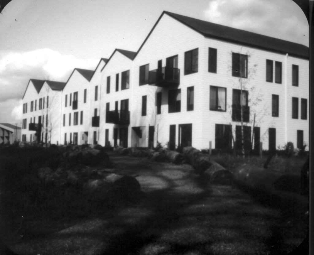
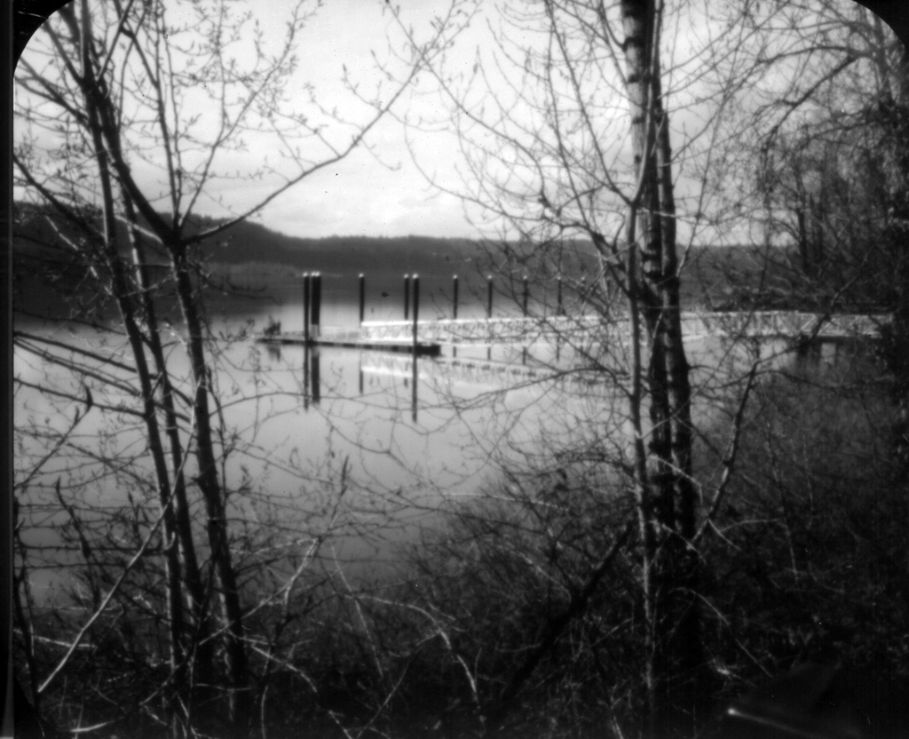
Finally, a few photos made with this camera, created by scanning and inverting
4"x3.33" paper negatives at 300 dpi. All images here are resized about 1024 x
832 pixels at 75 dpi for better viewing on a typical computer monitor.


If you've managed to read thus far, I hope you've got some inspiration and
may be some ideas how to build even better pinhole camera. Let me know what you think, I'm
always eager to learn as there's always next project waiting ahead. Good luck with your
own project!

Published on April 24 2025
Copyright© Victor Tikhonov, 2025