 July 01 2011
 July 01 2011
Motor shaft coupler
A design of the coupler between motor shaft and differential's pinion gear shaft for my car is unconventional. The reason is - there are no adapter plates, so there is no rigid connection between shafts. They're directly linked together, but because inevitable relative movement of the differential and motor (each sits on own rubber vibration isolators), the link must be flexible. The challenge is that there is no room for U-joints, CV joints and other such couplers between motor shaft and diff. For this reason stock motor shafts have to be shortened. Looking at various designs of OEM flex drive shaft couplers I chose the one used in Mercedes models - rubber disc that transmits torque and allows some angle misalignment. The stock disc has 3 attachment points (120° apart) to the drive shaft and another 3 points - to the differential. Stock Toyota differential pinion shaft has flange with 4 holes 90° apart. So this flange has to be re-machined and new coupler for the motor shaft designed and fabricated so that it mates with rubber coupler. Since the motor shaft is splined at its end which will be cut off, the motor shaft coupler will be machined undersized with interference meant to heat shrink it onto the motor shaft. It may be hard to believe, but experts say that properly designed, such way of joining shafts and hubs can be stronger than weld. The amount of interference is critical. In my case because of three different diameters of the motor shaft end (cascading down) and different amount of metal around, the optimal interference value had to be determined for each section of the shaft that has own diameter. Too much interference is not good - if the steel will not crack, it will cold flow and stretch still giving only so much gripping force. The temperature to heat the hub to (and shrink the shaft) can be determined from metallurgy data book and should be just enough to clear the interference so the hut hub can freely slip onto the frozen (e.g. shrunk) shaft, but not more. Needless to say the measurements and machining have to be done very accurate. My tooling allowed it to be +/-0.01mm. For my design I used 1018 steel and design required to have 0.04mm to 0.08mm interference in different sections of the shaft. To heat shrink I heated the hub to 300°C on the propane burner and cooled the shaft to -78'C with dry ice. The hub ended up slipping onto the shaft with some room to spare and whole process worked out perfectly. Here are detailed steps of making this all happen. Granted, for two identical drives I had to do everything described below twice.
![]() Blank steel rod about to loose most of its weight and become the
hub.
Blank steel rod about to loose most of its weight and become the
hub.
![]() 3 spokes 120° apart and rough outer shape were made on this CNC
mill. The photo of the CNC display with the job file loaded.
3 spokes 120° apart and rough outer shape were made on this CNC
mill. The photo of the CNC display with the job file loaded.
![]() The job has started.
The job has started.
![]() About half way in progress...
About half way in progress...
![]() ...Continuing on precision lathe.
...Continuing on precision lathe.
![]() Precision turning undersized inner bore of the hub that follows the
shape of the motor shaft stub.
Precision turning undersized inner bore of the hub that follows the
shape of the motor shaft stub.
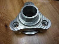
![]() The part is completed. The
holes are threaded with M10x1.0 thread.
The part is completed. The
holes are threaded with M10x1.0 thread.
Critical step 1: preparing the motor shaft.
![]() The shaft end was cut off with ordinary angle grinder. To make
straight cut the shaft was rotated by a cordless drill while being cut out.
The shaft end was cut off with ordinary angle grinder. To make
straight cut the shaft was rotated by a cordless drill while being cut out.
![]() Operation completed. Splined section is off.
Operation completed. Splined section is off.
![]() Photo of the coupler and
the shaft stub. Surface was cleaned - having it greased would be last thing I'd wanted.
Photo of the coupler and
the shaft stub. Surface was cleaned - having it greased would be last thing I'd wanted.
![]() Checking for
interference. 0.04mm undersized at the first section. Of course it should not quite fit on
(and it doesn't!).
Checking for
interference. 0.04mm undersized at the first section. Of course it should not quite fit on
(and it doesn't!).
Critical step 2: thermal operation followed shaft preparation is shown.
![]() To help the process the
shaft stub was frozen by dry ice to...
To help the process the
shaft stub was frozen by dry ice to...
![]() ...nearly -80°C, so it shrunk in diameter to ease putting on
expanded hub.
...nearly -80°C, so it shrunk in diameter to ease putting on
expanded hub.
![]() Making sure dry ice is in good contact with the shaft stub (38MB QT
movie file).
Making sure dry ice is in good contact with the shaft stub (38MB QT
movie file).
![]() At the same time the hub was heated on regular propane burner to
about +300°C so its diameter increased by more than 0.04mm - enough to put it onto the
frozen shaft stub freely.
At the same time the hub was heated on regular propane burner to
about +300°C so its diameter increased by more than 0.04mm - enough to put it onto the
frozen shaft stub freely.
![]() Preheated (and
expanded) hub was dropped onto the shaft. It slipped on easily !
Preheated (and
expanded) hub was dropped onto the shaft. It slipped on easily !
![]() The end of the shaft - its color changed after being heated by the
hub.
The end of the shaft - its color changed after being heated by the
hub.
![]() I used angle grinder
to grind off the end of the shaft to desired length. The shaft was slowly rotating while
being ground down.
I used angle grinder
to grind off the end of the shaft to desired length. The shaft was slowly rotating while
being ground down.
![]() The end result is
pretty impressive.
The end result is
pretty impressive.
![]() Trial fit of the
flex disc with differential pinion shaft flange on top.
Trial fit of the
flex disc with differential pinion shaft flange on top.
![]() This is how the
whole flex joint is going to look like. Differential is placed on top to make some
measurements before putting whole assembly under the body.
This is how the
whole flex joint is going to look like. Differential is placed on top to make some
measurements before putting whole assembly under the body.
As I mentioned, I had to go through all this endeavor twice preparing identical front and rear setups. That makes it a bit easier as far as coupler goes, but suspending front and rear differentials will require very different brackets covered in the couple of following pages. described...
![]()