 March 14 2009
 March 14 2009
Battery. (This page has been superseded by updated battery design)
The battery. Everyone talks about the battery. It is your biggest concern, biggest expense and the whole EV is only as good as its battery. Typically it is also the biggest limitation in your EV, underscoring its utility. The battery is the only disposable item in the car you will replace sooner or later (for the same or different type) and keep replacing it if you keep your EV long enough. Sort of like an oil change in conventional engine: no matter how gently you drive, it wears out. There are so many choices, and at the same time - really so few that are worthy, at least at the time of this writing. After experimenting with Lead acid, NiMH, LiIon and now LiPo chemistries, it is quite clear that there are two winners here: NiMH and Lithium based battery chemistry, capable of delivering power and energy a practical EV demands. But this is from a technical point of view. The reality is, there are political, economical and other reasons for advancing or suppressing what is best overall, so I'm not going to debate why you cannot have for instance and excellent GM Ovonic NiMH battery in your EV you'd buy in local autoparts store as any other lead acid battery. Ask GM why not. I'll focus on Lithium which is a common type of battery made in millions of units for all kinds of gadgets and applications, and in recent years was scaled up enough to become the battery of choice for more-or-less advanced freeway capable EVs.
Here is a brief run down on the particular chemistry flavors (mainly differentiated by the cathode material):
- Lithium Ion (LiIon)
- Lithium Manganese (LiMn)
- Lithium Cobalt (LiCo)
- Lithium Polymer (LiPO)
- Lithium Iron Phosphate LiFePO4)
I'm sure other fancier materials will appear in future as well as better manufacturing
processes (such as Nano-technologies, basically drastically increasing the chemical
reaction area)
LiIon is the oldest and most mature technology but it fell out of fashion due to relatively unstable properties and not as good power and energy density as other options. There is plenty of info out there comparing different types of batteries; sometimes objective, but most often biased (e.g. released by the battery manufacturer or worse - battery salesmen). I'm going to concentrate on LiPo choice for Audi - as you know from the simulation page this is the battery I'll use. As this page is not meant for academic education but rather just a description of what I did, I will only briefly compare LiPO type cells with the now fashionable LiFePO4 everyone seems to crave for. What are the advantages of LiFePO4? It is considered a safer battery in case you abuse it (in an accident or by inadvertent mistreatment via wrong charging or discharging). Manufacturers will blatantly tell you that their perfect battery will not catch fire as LiFePO4 is almost immune to it. Of course, it's a lie. In manufacturer's tests orchestrated to prove the point (read - boost sales) this might be the case - i.e. if LiFePO4 and other types of batteries are placed in an environmental chamber and the conditions (overcharging or high temperature) are gradually made harsher to see which type fails first. Say, if a LiFePO4 cell is compared to LiPo one. The LiFePO4 cell resists abuse longer (tolerates higher temperature before trouble occur). Once conditions are reached such that the LiPo fails or catches fire, the test stops and LiFePO4 is declared a winner since it didn't catch fire. However, if the conditions get worse, the LiFePO4 cell would burn just as cheerfully. Don't believe me? Check out this link accompanied with these photos - this was a vehicle equipped with a LiFePO4 pack that "never burns". Whether the owner made a mistake or the charger failed to stop, it's unclear, but this is beside the point. The point is, ANY presently known battery will burn and or ignite its surroundings as long as it contains energy which has to go somewhere. Where else can it go in not to the heat? It's pure physics no matter what a battery salesmen will tell you. The LiFePO4 chemistry may well be relatively safer than LiPo or others, but the bottom line is - it is not immune to fire and at right conditions still burns very well. You're welcome to copy these images, and next time a sales rep tries to sell you safe LiFePO4 battery, show them this proof and ask if they will bet their life or at least their salary on the fact that LiFePO4 is impossible to ignite and watch his reaction. It's fun.
Another reason everyone runs after LiFePO4 - most of the batteries of this type are made in China, so it can be bought cheap. For instance take the famous Thunder-Sky who used to sell crap (ask me how I know), but is evidently producing more reliable product these days. Economics aside, let's compare the most important parameters relevant for your EV. Fundamentally, what do you want from your battery?
- Move your EV far enough (whatever YOUR definition of
"far enough" is).
- Be powerful enough
- Able to get charged fast.
- Last long time ("long" means as close to the live of the vehicle itself as
possible, ideally 10 years or so).
- Be safe
- Be physically light and small
- Be maintenance free (install and forget)
- Be a commodity (readily available from multiple sources)
- Provide sense of confidence in its performance, typically based on reputation which in
turn is based on someone else's previous experiences,
- Be cheap
- Be cheap
- Be cheap
Last three points contradict (and always will contradict) all other points. But don't flip this priority list up side down - your EV won't get very far.
Basically you want all the qualities above but don't want to pay a lot of money for them. OK, lets get to reality and as with everything in life, compromise. Don't expect me to define the "best" combination here, it's the same as trying to tell you what's the best vehicle out there in general. It all depends on how much value you personally assign to each of these qualities and how you prioritize them. Only you know that.
In my case what I looked for is basically one main parameter - energy density. This is because I wanted the highest capacity with minimal weight. The size of the battery then becomes a compromise between how far I can drive on one charge and how much battery I can afford. LiPo is the winner as far as gravimetric energy density (its Wh/kg ratio is higher than that of LiFePo4). I want to raise the voltage high enough and that dictates the number of cells. I'll target a battery consisting of 192 cells. Why 192? Because I will have 6 blocks of 32 cells each. 32 cells make up 118V block and that voltage has some advantages. Another choice is to have 48V blocks which depending on the BMS choice may be even more advantageous, but I'll have to start somewhere and then experiment later.
Here are my thoughts. Any battery (well, actually
everything surrounding us in life) is affected by the temperature. There are two choices
to deal with this:
a) adapt the charging / discharging conditions to the actual temperature of the battery,
compensating affected parameters per the manufacturer's recommendations (if they have
any...);
b) maintain about the same battery temperature regardless of the ambient temp. Then you
don't have to deal with the above, but you need extra effort (and hardware) to implement
it.
There may be a combination of both.
I chose method b) above. Basically, its cycle life will not be affected by the temperature, and thermal control is electrically trivial to do. The trick is to provide good thermal contact with the individual cells. As with everything in the Audi, the battery will be liquid cooled (it's a customary expression, since sometimes the battery will be liquid-warmed rather than cooled). Air cooling will require a larger battery (gaps between cells for air circulation), ducts, noisy fans, etc. The arguments are pretty much the same as for water cooled vs. air cooled motor.
After debating how the BMS is going to fit and how to take care of thermal issues, an initial concept materialized and got captured in my work book. Basically, because the cells are sealed in poly pouch and have soft tab terminals, it presents challenge to hold them in place - there is no place you can bolt to, not even the terminals. So in each box the cells will be staked in a row and one large thick base PCB will cover all of them. The tab terminals will be inserted through the long cutouts in the base PCB, folded above and clamped between aluminum bars. The BMS boards will be positioned vertically and inserted into the connectors on the base PCB. This allows replacement of the BMS boards with a different type without touching the box. There will be heat sinking aluminum sheets between the cells; they extend beyond the sides and are clamped between spacers equal to the cell thickness. These spacers will be bolted to the aluminum sides with a machined water path. There are seal sheets between the machined sides and the spacers, forming a hermetic channel when squeezed together. To ensure no leaks, there is a grove and O-ring around the bolts holding the sides. That's the plan. It's easier to see than explain, so here are photos of what I did:
![]() Concept of the battery construction.
Concept of the battery construction.
![]() In the mean time the cells were ordered. They arrived in a few
large crates, straight from Kokam Korea.
In the mean time the cells were ordered. They arrived in a few
large crates, straight from Kokam Korea.
![]() The cells are about size of a notebook, just square. Another
challenge upon closer inspection: they are not quite equal thickness across. They are
thicker towards the terminal tabs, thinner towards the bottom.
The cells are about size of a notebook, just square. Another
challenge upon closer inspection: they are not quite equal thickness across. They are
thicker towards the terminal tabs, thinner towards the bottom.
![]() The soft tabs are 0.2mm thick. One is made of nickel and the other -
of nickel alloy. One is softer and more easily bent than the other. They are flat so I
will need a jig to cut the tabs to size and punch holes.
The soft tabs are 0.2mm thick. One is made of nickel and the other -
of nickel alloy. One is softer and more easily bent than the other. They are flat so I
will need a jig to cut the tabs to size and punch holes.
![]() All the construction planning is of course is done in CAD allowing
to check the proper fit. About 20 iterations later final drawings were done.
All the construction planning is of course is done in CAD allowing
to check the proper fit. About 20 iterations later final drawings were done.
![]() I made a simple jig to trim the tabs. Careful, the jig cannot be all
metal, and it can touch only one terminal at the time!
I made a simple jig to trim the tabs. Careful, the jig cannot be all
metal, and it can touch only one terminal at the time!
![]() After a few days of work all the tabs were cut and punched, and the
cells were stacked to get ready for assembly into the pack.
After a few days of work all the tabs were cut and punched, and the
cells were stacked to get ready for assembly into the pack.
There are quite a few parts that had to be made to accomplish the design goals. For mass manufacturing this may not be the optimal design, but for a few boxes and initial proof of concept it's worth the trouble. The trick is to use as close to stock material as possible - this will minimize machining time and expense. Here is what was made:
![]() Top and bottom tab terminal clamps. Top one will also hold a cell's
BMS PCB.
Top and bottom tab terminal clamps. Top one will also hold a cell's
BMS PCB.
![]() Spacers. There are 5 groups with staggered holes. This is done to
spread the compression and distribute the heat as evenly as possible across the entire
sides of a box.
Spacers. There are 5 groups with staggered holes. This is done to
spread the compression and distribute the heat as evenly as possible across the entire
sides of a box.
![]() Front and rear "book ends" and left and right sides were
machined for all the boxes. Beautiful work.
Front and rear "book ends" and left and right sides were
machined for all the boxes. Beautiful work.
![]() The end terminals connecting the first and last cells to box studs -
these will be + and - of the box.
The end terminals connecting the first and last cells to box studs -
these will be + and - of the box.
![]() Stack of heat sink sheets with holes punched along the edges.
Stack of heat sink sheets with holes punched along the edges.
![]() The
insulating plates holding bolts (studs) CNC machined from 12.7mm thick polycarbonate.
The
insulating plates holding bolts (studs) CNC machined from 12.7mm thick polycarbonate.
![]() Bare base PCB overview.
Bare base PCB overview.
![]() Same PCB populated with connectors and bottom clamps bolted on.
Same PCB populated with connectors and bottom clamps bolted on.
![]() The tab routed BMS PCBs. On this photo only SMT components are
populated.
The tab routed BMS PCBs. On this photo only SMT components are
populated.
![]() Precise calibration of the DC-DC converter of a node - this is the
fixed final voltage any cell will be charged up to.
Precise calibration of the DC-DC converter of a node - this is the
fixed final voltage any cell will be charged up to.
![]() Tedious
and repetitive work, but one after another, all the nodes were SMT assembled, and then
calibrated by hand. Here the trim pots are being fixed with LockTite.
Tedious
and repetitive work, but one after another, all the nodes were SMT assembled, and then
calibrated by hand. Here the trim pots are being fixed with LockTite.
![]() Here I got help to pre-assemble the nodes. The top clamp was bolted
to each node.
Here I got help to pre-assemble the nodes. The top clamp was bolted
to each node.
![]() Finally the electronics were tested and ready to be installed! There
are two [mirror] layouts of the same circuit - right and left. This is due to the fact
that even and odd cells have terminals facing different directions (say, even - positive
to the left, and odd- positive to the right looking from one book end), but the PCBs have
components on one side - toward one end (not an alternating orientation). Again, it will
be easier to see below than explain.
Finally the electronics were tested and ready to be installed! There
are two [mirror] layouts of the same circuit - right and left. This is due to the fact
that even and odd cells have terminals facing different directions (say, even - positive
to the left, and odd- positive to the right looking from one book end), but the PCBs have
components on one side - toward one end (not an alternating orientation). Again, it will
be easier to see below than explain.
That's all regarding parts. Now, the fun part - assembly.
Initially I assembled the first box stacking up the cells. This worked OK, but it was difficult to align them all and after assembly it turn out the row of cells is not quite parallel to the aluminum side, and thus neither is the base PCB sitting right on top of each cell against their top seam:
![]() Initially checked to see if the tabs freely go through the cutouts,
don't touch anything they're not suppose to and verified clearances. So far so good.
Initially checked to see if the tabs freely go through the cutouts,
don't touch anything they're not suppose to and verified clearances. So far so good.
![]() Close up photo - the tab will be bent over the bottom clamp...
Close up photo - the tab will be bent over the bottom clamp...
![]() ...and squeezed between it and the top clamp. Another tab from the
adjacent cell will be inserted between the clamps from the opposite side (not shown here).
The bolt here is loose, just to see the overall fit.
...and squeezed between it and the top clamp. Another tab from the
adjacent cell will be inserted between the clamps from the opposite side (not shown here).
The bolt here is loose, just to see the overall fit.
I started assembly on a plank of wood, laying down the bottom bookend and stacking the cells up. An insulating sheet was cut and placed on each cell covering its terminals right before an aluminum sink sheet was placed onto the threaded rods against that cell. This is to prevent shorting of the cell's tabs by the sink.
![]() One bookend is first and then the first cell is on top. Its tabs are
inserted into the slots in the base PCB. Stainless steel rods will line up everything and
tighten the big sandwich at the end of assembly.
One bookend is first and then the first cell is on top. Its tabs are
inserted into the slots in the base PCB. Stainless steel rods will line up everything and
tighten the big sandwich at the end of assembly.
![]() Next go the side spacers.
Next go the side spacers.
![]() Next - heat sink, another cell, heat sink, and so on. Granted, the
cells are alternating face up and face down to get the terminals interconnected in series.
I decided to place spacers in after all the cells are stacked up.
Next - heat sink, another cell, heat sink, and so on. Granted, the
cells are alternating face up and face down to get the terminals interconnected in series.
I decided to place spacers in after all the cells are stacked up.
![]() Half way through. You can see the tabs sticking out of the slots in
the base PCB. Careful - if they bend - they short. If they short - the tabs will act as
fuses and spectacular arcing destroying the tabs will accompany the show.
Half way through. You can see the tabs sticking out of the slots in
the base PCB. Careful - if they bend - they short. If they short - the tabs will act as
fuses and spectacular arcing destroying the tabs will accompany the show.
![]() Same photo from the side.
Same photo from the side.
![]() After the last cell is in place, the top book end goes on last.
After the last cell is in place, the top book end goes on last.
As I mentioned, after tightening the rods I realized the stack is not exactly vertical. It is nearly impossible to press (and keep pressing) each cell against the base PCB during assembly. It had to be done another way. I decided to put them all on a jig, and assemble the box upside down, so each cell will be laying on top of the base PCB and they will all line up under their own weight as long as the base PCB is flat. Well, this is what the jig is for - it holds the edges of the base PCB along the long sides allowing the cell tabs to get between the sides. I have to adjust the gap between the jig's sides to be about 1mm wider than the distance between the outside edges of the tabs. This proved to be just enough. Here:
![]() The jig. Not very high tech, but very handy and does the job.
The jig. Not very high tech, but very handy and does the job.
![]() The
aluminum sides and threaded rods are prepared.
The
aluminum sides and threaded rods are prepared.
![]() The base PCB is on the jig face down. First book end is positioned
and threaded rods are inserted.
The base PCB is on the jig face down. First book end is positioned
and threaded rods are inserted.
![]() This time the spacers will be placed together with each cell, not
after assembly.
This time the spacers will be placed together with each cell, not
after assembly.
![]() Preparing the first cell. The tabs are soft so I needed to watch out
not to bend them. Not visible on the photo, but there is clear plastic between the tabs
and the aluminum book end prevent an electric short.
Preparing the first cell. The tabs are soft so I needed to watch out
not to bend them. Not visible on the photo, but there is clear plastic between the tabs
and the aluminum book end prevent an electric short.
![]() The cell tabs are inserted half way into the base PCB.
The cell tabs are inserted half way into the base PCB.
![]() The plastic insulator sheet is visible here.
The plastic insulator sheet is visible here.
![]() Installing the heat sink separator sheet.
Installing the heat sink separator sheet.
![]() It is pressed against the first cell, and
insulating sheet is
placed on right after this step - so that if the next cell's tabs touch the separator
before getting into the slot in the base PCB, they will not be shorted.
It is pressed against the first cell, and
insulating sheet is
placed on right after this step - so that if the next cell's tabs touch the separator
before getting into the slot in the base PCB, they will not be shorted.
![]() Next
go the side spacers.
Next
go the side spacers.
![]() Next the sink separator sheet.
Next the sink separator sheet.
![]() ...and so on. Half way through.
...and so on. Half way through.
![]() Last cell is placed.
Last cell is placed.
Because all the cells are up side down (terminals facing down), their weight automatically aligns them all on the base PCB. The PCB rests on the jig, so as long as the jig is straight, the assembly is as ideal as it can be; each cell protrudes through the PCB the same amount so the holes in the tabs will line up with the holes in the clamps after folding. This is important because I don't want to accommodate inaccuracy by oversizing the punched holes thus reducing the contact area of the tabs. The bolts clamping the tabs are M5 and the holes are 6.35mm diameter - just enough slack but not too much missing material around the holes.
![]() The view from the bottom. You can see that the cell tabs just fit
between sides of the jig with no gaps.
The view from the bottom. You can see that the cell tabs just fit
between sides of the jig with no gaps.
![]() The second book end is put onto the rods.
The second book end is put onto the rods.
![]() Side view. The whole stack can wobble side to side easily, which is
good at this point - doing so self-aligns the cells settling everything into place.
Side view. The whole stack can wobble side to side easily, which is
good at this point - doing so self-aligns the cells settling everything into place.
![]() This is critical - every so many cells I inserted thick foil shims
to get the total cell+shim thickness to be slightly more than the thickness of side
spacers. Because only friction holds the cells in place, I need to make sure that when the
stack is tightened, the cells are going to be squeezed hard, not the spacers. Because of
the thickness tolerances, choosing the amount of shimming is a trial and error process.
Trying to compress the stack reveals whether the cells or spacers are going to get
squeezed the hardest.
This is critical - every so many cells I inserted thick foil shims
to get the total cell+shim thickness to be slightly more than the thickness of side
spacers. Because only friction holds the cells in place, I need to make sure that when the
stack is tightened, the cells are going to be squeezed hard, not the spacers. Because of
the thickness tolerances, choosing the amount of shimming is a trial and error process.
Trying to compress the stack reveals whether the cells or spacers are going to get
squeezed the hardest.
![]() Another place for shim installation.
Another place for shim installation.
![]() Initial compressing of the stack. The goal here is to line up the
staggered holes in the spacers with the holes in the seal sheets and the machined sides.
Initial compressing of the stack. The goal here is to line up the
staggered holes in the spacers with the holes in the seal sheets and the machined sides.
![]() A couple of adjustable C-clamps allow squeezing the right and left
side independently.
A couple of adjustable C-clamps allow squeezing the right and left
side independently.
![]() Making
sure the stack is true rectangular.
Making
sure the stack is true rectangular.
![]() The side seal goes first.
The side seal goes first.
![]() Whoops, forgotten thread for the inlet fitting. Fixed.
Whoops, forgotten thread for the inlet fitting. Fixed.
![]() Regular Teflon tape around NPT thread of the fitting.
Regular Teflon tape around NPT thread of the fitting.
![]() The
fitting being installed.
The
fitting being installed.
![]() All 4 fittings are installed on the front book end. Later on the
excessive rods ends will be cut off.
All 4 fittings are installed on the front book end. Later on the
excessive rods ends will be cut off.
To make sure no water leaks occur, an O-ring will be installed. First a sealing compound is applied into the groove for the O-ring. The ring (2.3mm diameter) is thicker that the groove depth (1.6mm), so the ring is squeezed to guarantee a good seal. To fill all the microscopic gaps between the aluminum and the rubber, compound is a sealing compound is a good idea. It also seals the gap where the ends of the rubber cord meet butt-to-butt (it is not a pre-made O-ring but a stock rubber cord on a spool).
![]() Filling the grove with sealing compound.
Filling the grove with sealing compound.
![]() Placing the cord at an arbitrary starting point.
Placing the cord at an arbitrary starting point.
![]() It follows a serpentine grove.
It follows a serpentine grove.
![]() The amount of compound is liberal enough to get squeezed out and
cover the ring from the top. Now it is ready for the side installation.
The amount of compound is liberal enough to get squeezed out and
cover the ring from the top. Now it is ready for the side installation.
![]() The side with the O-ring lined up with the seal sheet.
The side with the O-ring lined up with the seal sheet.
![]() Both are placed on their side and bolted to the spacers. Of course
the bolt pattern in the machined side matches the pattern formed by the stacked spacers.
Same story on the other side.
Both are placed on their side and bolted to the spacers. Of course
the bolt pattern in the machined side matches the pattern formed by the stacked spacers.
Same story on the other side.
![]() Let's test for leakage. No problem after 1 hour.
Let's test for leakage. No problem after 1 hour.
![]() Turning the box on one side. Now I can deal with the tabs.
Turning the box on one side. Now I can deal with the tabs.
Time to do electric interconnects. The softer positive tab is bent first as it is easier to get into a sharper radius. The negative tab of the adjacent cell goes over top. At this point I must be careful as all the cells become connected in series and there is 118V between the end cells. And, it's about 4.7kWh worth of energy, so if this thing shorts, spectacular fireworks are guaranteed.
![]() Bending the tabs over the bottom clamps.
Bending the tabs over the bottom clamps.
![]() Installing
the BMS PCBs. They are bolted to the top clamp.
Installing
the BMS PCBs. They are bolted to the top clamp.
![]() Inserting
the connector into the mating part on the base PCB. The top clamp (held by three M3 bolts)
will prevent it from ever disengaging.
Inserting
the connector into the mating part on the base PCB. The top clamp (held by three M3 bolts)
will prevent it from ever disengaging.
![]() I made an error in the layout (which was not feasible to predict) -
one of the bolts holding the clamp when unbolted is interfering with the transformer on
the PCB. Assembled, there is no problem, but getting to this bolt is difficult. So I had
to make this tool by grinding an L-Allen key. This error is already fixed for future PCBs
of this type, but for now I have to deal with all the boards already made this way.
I made an error in the layout (which was not feasible to predict) -
one of the bolts holding the clamp when unbolted is interfering with the transformer on
the PCB. Assembled, there is no problem, but getting to this bolt is difficult. So I had
to make this tool by grinding an L-Allen key. This error is already fixed for future PCBs
of this type, but for now I have to deal with all the boards already made this way.
![]() Installing
the end terminal connecting the first tab to the stud.
Installing
the end terminal connecting the first tab to the stud.
![]() Another
photo of this. Two bolts are enough to make reliable contact.
Another
photo of this. Two bolts are enough to make reliable contact.
![]() The
terminal plate is ready.
The
terminal plate is ready.
![]() Tightening the nut over the end terminal. The stud is an M12
stainless steel bolt with machined head. The head is recessed into the polycarbonate plate
so doesn't touch the aluminum book end.
Tightening the nut over the end terminal. The stud is an M12
stainless steel bolt with machined head. The head is recessed into the polycarbonate plate
so doesn't touch the aluminum book end.
![]() This box is the first (the most negative) in the chain, so the
battery shunt gets installed here. Note, the stainless steel bolts everywhere were only
used for mechanical strength - they do not conduct electric current.
This box is the first (the most negative) in the chain, so the
battery shunt gets installed here. Note, the stainless steel bolts everywhere were only
used for mechanical strength - they do not conduct electric current.
![]() Another photo of the shunt installation.
Another photo of the shunt installation.
![]() Some nodes are equipped with a thermistor touching the part of the
special separator plates that have a narrow neck protruding through the special cutout in
the base PCB. The thermistor can touch this neck thus measuring the temperature of the
separator. However, this proved to be redundant as the water temperature is a very good
indicator of the pack temperature. Overheating of individual cells is undetectable by
these thermistors and will have to be identified by the cell behavior under load. So most
of the nodes were not equipped with thermistors although electronic circuitry is there to
do it, just in case. I will see how useful this circuitry is.
Some nodes are equipped with a thermistor touching the part of the
special separator plates that have a narrow neck protruding through the special cutout in
the base PCB. The thermistor can touch this neck thus measuring the temperature of the
separator. However, this proved to be redundant as the water temperature is a very good
indicator of the pack temperature. Overheating of individual cells is undetectable by
these thermistors and will have to be identified by the cell behavior under load. So most
of the nodes were not equipped with thermistors although electronic circuitry is there to
do it, just in case. I will see how useful this circuitry is.
![]() All the nodes are lined up nicely. Turn out to be very sturdy
arrangement.
All the nodes are lined up nicely. Turn out to be very sturdy
arrangement.
Finally, the box assembly is completed. It is checked for water leaks and next must be electrically tested. The stack was charged a bit and the BMS activated. The cells came from the factory amazingly uniform, the voltage difference between cells was no more than 0.02V. So there was no point to balance the pack, I just needed to make sure all the circuitry functions as designed. A yellow LED indicates balancing charging is taking place individually per cell. And because the pack is not full (each cell is less than 4.15V), every node should be active trying to bring its cell to that voltage level. So, this is easy to check - all yellow LEDs must be on as soon as balancing is enabled.
![]() Test of assembled pack. It's hard to see the LEDs, but they are all
ON.
Test of assembled pack. It's hard to see the LEDs, but they are all
ON.
![]() Another view of the box and the BMS being tested.
Another view of the box and the BMS being tested.
![]() This photo is prettier - taken without flash.
This photo is prettier - taken without flash.
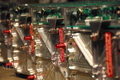
![]() Well, this is about it. All I need now is to repeat all of the
procedures described above six more times and my battery will be done. On this photo only
4 boxes are completed.
Well, this is about it. All I need now is to repeat all of the
procedures described above six more times and my battery will be done. On this photo only
4 boxes are completed.
![]() Another view of the completed battery ready to be installed. They
turn out to be quite OEM looking and worthy of my electric Audi A6.
Another view of the completed battery ready to be installed. They
turn out to be quite OEM looking and worthy of my electric Audi A6.
Next will be the charging solution and I need to settle on the drive system. There are quite a few things to do in the vehicle that are independent of the drive system, so this will allow me to wait before making a final choice and not delay completion of the project. I must take a break to prepare for the trip to EVS-24 in Norway which is about 3 weeks away, and will resume when I come back. So if you like what you see so far, stay tuned.
![]()