LED lighting
 Now, the fun part. All the external lights except the head
lights and the front markers are LED clusters. The advantage I see
is high reliability (LEDs won't burn out), low current consumption,
consistent pure colors and distinctive look. Another thing I took
advantage of - arranging the rear lights LEDs into a matrix display
allowing to indicate the status of the chargers without even coming
close to the car. More on that - below. So, my stop lights, side
markers, parking lights, and turn signals are in new form now.
Amber in front and red in the back.
Now, the fun part. All the external lights except the head
lights and the front markers are LED clusters. The advantage I see
is high reliability (LEDs won't burn out), low current consumption,
consistent pure colors and distinctive look. Another thing I took
advantage of - arranging the rear lights LEDs into a matrix display
allowing to indicate the status of the chargers without even coming
close to the car. More on that - below. So, my stop lights, side
markers, parking lights, and turn signals are in new form now.
Amber in front and red in the back.
Well, there is more
serious reason for doing it: LEDs turn on about 100ms quicker than
incandescent light bulb. While doesn't sound a lot, at 65 mph the
car goes about its body length in this 0.1 second. So if I see the
obstacle on the road and hit the brakes, if the driver behind will
react 0.1 second earlier hitting his brakes, all else being equal
he will stop a full car length further from me. This simply means
that if in such extreme case he stops 2-3 feet from my car, if I
wouldn't have LEDs, he would "kiss" my rear bumper...
 So the first step - taking stock lights
off and make room for the PCB with the matrix of LEDs mounted on
it. I started with rear combo lights. On my Honda whole assembly is
made of plastic so it is easy to cut away the spherical sections
holding the light bulbs and making the surface smooth enough.
Dremel tool is of big help here. When all the lights are prepared
and cleaned out, I measured the size of the available area inside
and cut the carton template to see how it fits in the light shell.
After trimming it I got exact size of the PCB to be made. Well, I
ended up using perforated prototyping board, which in a way was a
mistake - it tripled amount of work to interconnect all the LEDs in
right sequence. If I were to do it again, the PCB is the way to go.
Anyway, after all the LEDs were arranged in the nice rows and
soldered in, they were connected in series of 2, 3, 4, 5 and 6 with
the current limiting resistors. The chains with two LEDs start
glowing first (at about just 5V). When the voltage increased, the
groups of 3 LEDs come on, then 4 LEDs, etc. At 14.2V they all lit
at full brightness with 20mA of the current through each chain.
These are high output LEDs (red ones are 7000 mCd, amber are 9000
mCd) so it may be painful to look from the close distance to all of
them lit.
So the first step - taking stock lights
off and make room for the PCB with the matrix of LEDs mounted on
it. I started with rear combo lights. On my Honda whole assembly is
made of plastic so it is easy to cut away the spherical sections
holding the light bulbs and making the surface smooth enough.
Dremel tool is of big help here. When all the lights are prepared
and cleaned out, I measured the size of the available area inside
and cut the carton template to see how it fits in the light shell.
After trimming it I got exact size of the PCB to be made. Well, I
ended up using perforated prototyping board, which in a way was a
mistake - it tripled amount of work to interconnect all the LEDs in
right sequence. If I were to do it again, the PCB is the way to go.
Anyway, after all the LEDs were arranged in the nice rows and
soldered in, they were connected in series of 2, 3, 4, 5 and 6 with
the current limiting resistors. The chains with two LEDs start
glowing first (at about just 5V). When the voltage increased, the
groups of 3 LEDs come on, then 4 LEDs, etc. At 14.2V they all lit
at full brightness with 20mA of the current through each chain.
These are high output LEDs (red ones are 7000 mCd, amber are 9000
mCd) so it may be painful to look from the close distance to all of
them lit.
 Rear combo lights (back side). Yellow turn, red
stop, two red rear markers and one red side marker.
Rear combo lights (back side). Yellow turn, red
stop, two red rear markers and one red side marker.
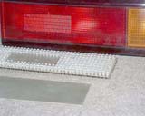
 The bulbs are removed and the plastic
is milled out with Dremel tool to expose the lens. Half way done
here.
The bulbs are removed and the plastic
is milled out with Dremel tool to expose the lens. Half way done
here.
 The piece of prototyping PCB with the
matrix of the LEDs soldered in their position. About 200 LEDs make
up rear brake and parking light here.
The piece of prototyping PCB with the
matrix of the LEDs soldered in their position. About 200 LEDs make
up rear brake and parking light here.
 Zoomed in view of the LED matrix.
 Side view of the turn light PCB with
yellow LEDs. Note different angles LEDs are facing.
Side view of the turn light PCB with
yellow LEDs. Note different angles LEDs are facing.
 Both PCBs are connected to the original
harness - front view.
Both PCBs are connected to the original
harness - front view.
 Both PCBs are connected to the original
harness - back view.
Both PCBs are connected to the original
harness - back view.
 Front turn lights PCBs - front and back
view.
Front turn lights PCBs - front and back
view.
 The same - side view (before
interconnecting LEDs)
The same - side view (before
interconnecting LEDs)
 PCBs installed into the plastic shell.
Note turn light PCB is installed at about 45 degrees angle.
PCBs installed into the plastic shell.
Note turn light PCB is installed at about 45 degrees angle.
 Close up of above.
The same
modification was done for the front lights (marker and turn) and
the rear central . Special attention has to be paid to the
protection from the moisture that will corrode the soldering joints
over time. I've used RTV silicon compound made by GE - great stuff
for keeping the water out. Entire shell is covered from inside and
when the compound "hardened" you probably could use the light
underwater - nothing should happen to it.
The central brake light - front view.
The same - rear view.
The front turn signal light - small PCB
is installed and sealed with RTV compound. Yes, I can't easily
remove it, but when was last time you had to replace failed
LED?
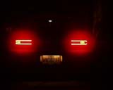
 Well, here are a few photos what the
result look like. It was very difficult to take an image of the
light source with a digital camera - I was unable to get red color
on the image from the red lights. Aura around is red but the LEDs
turn out to be white - may be camera's CCD got saturated or
something similar. Anyway, the white looking LEDs are actually red.
And, in the dark it is painful to look straight to the brake lights
from a short distance. Not all the possible lights are on the
photos, like single yellow charger status LED of two red "Failure"
LEDs. I'm sure you got the picture though. Here it is:
Well, here are a few photos what the
result look like. It was very difficult to take an image of the
light source with a digital camera - I was unable to get red color
on the image from the red lights. Aura around is red but the LEDs
turn out to be white - may be camera's CCD got saturated or
something similar. Anyway, the white looking LEDs are actually red.
And, in the dark it is painful to look straight to the brake lights
from a short distance. Not all the possible lights are on the
photos, like single yellow charger status LED of two red "Failure"
LEDs. I'm sure you got the picture though. Here it is:
The left charger is on.
The charger is off, but still is
plugged in (as when the charge is finished).
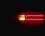
Rear marker light. It's red!
The turn light.
Hard to tell what it is, but this is
front side marker/turn light.
Front turn light
Brake and marker lights are on.
Overall view. Both chargers have
finished charging cycle and shut off. This info remains until
unplugged from AC mains.
Are you having fun?
If so, here are some more photos for you taken in the
dark:
Markers and chargers are on.
Marker and stop.
Marker and turn.
Just the rear marker. Small side marker
is visible too.
Close up "on"
Close up "off" and "plug"
Brakes are on.
Instrumentation
 Good instrumentation is essential to stay informed
of what is going on in the car. Despite common opinion, for
monitoring fluctuating values nothing beats a good analog meter.
Because of inertia of its movement, it averages out spikes and
noise in the measured signal so you get "filtered" output. Digital
displays have be updated and you have to think what are you seeing.
In analog meter you can use color backgrounds on the scale to
indicate acceptable or dangerous zones, so quick glance on it will
tell you the story instantly.
Good instrumentation is essential to stay informed
of what is going on in the car. Despite common opinion, for
monitoring fluctuating values nothing beats a good analog meter.
Because of inertia of its movement, it averages out spikes and
noise in the measured signal so you get "filtered" output. Digital
displays have be updated and you have to think what are you seeing.
In analog meter you can use color backgrounds on the scale to
indicate acceptable or dangerous zones, so quick glance on it will
tell you the story instantly.
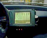
In my case the
inverter came with diagnostic software which allow to display any
inverter parameter on the PC screen in digital, analog or binary
(or any combination of these) form. Besides, I can select only
these instruments which display relevant for driving information.
As the PC and displaying module I use Fujitsu Stylistic 1200 pen
based computer with monochrome transflective screen. The main
advantage is that it is well visible in direct sun light, like a
digital wrist watch - the brighter the better. Of course, for dark
conditions there is backlit. So, what I have configured to be
displayed (and updated in real time as I drive) on the screen
is:
- Battery pack
voltage
- Battery current
- Battery power
- Motor power
- Motor torque
- Inverter's power stage (IGBTs) heat sink temperature
- DC-DC converter heat sink temperature
- Motor windings temperature (2 points)
- Acceleration pedal demand value
- Regen brake pot demand value
- Motor shaft speed (RPM)
- Error buffer status
Also all the same
info in digital form.
Overview of my dash board
Side view. Interface connections are
visible.
Close up of the Stylistic 1200 PC
mounted on the dash.
All I want to know about the status
of the system.
Any parameter can be changed on the
spot, taking effect as soon as I hit <ENTER>. Even while I
drive. Great for fine tweaks.
