The battery management system.
Not yet available, being developed by Metric Mind Engineering
 Perhaps anyone you will
talk to will tell you that LiIon technology is quite dangerous, exceeding max allowable
ratings for the battery may cause fire or even explosions, and perhaps quote you some
rumors claiming witnessing it. Is this true? The only valid answer is - it depends. It
depends on:
Perhaps anyone you will
talk to will tell you that LiIon technology is quite dangerous, exceeding max allowable
ratings for the battery may cause fire or even explosions, and perhaps quote you some
rumors claiming witnessing it. Is this true? The only valid answer is - it depends. It
depends on:
- Chemistry flavor (Li-Ion, Li- polymer,
Cr-F-Li)
- Presence of Lithium in a metal form
- Battery specific power (directly related to its stability)
AND THE MOST IMPORTANT ONE:
- How far and for how long you stretch recommended maximum parameters.
Once you obtained the battery, top three
items you have no control over, although you better know your battery to understand risks
and trade offs. The price for great energy and power density is instability - it is
natural that if you manage to pack greater amount of energy in the same volume/weight
(comparing to different chemistries), the more energy is going to be violently released in
case of trouble. I will discuss Cr-F-Li chemistry used by Chinese manufacturer Thunder-Sky
(TS) to manufacture its LiIon cells, since this is what I have.
The cells can be manufactured with high
specific energy or high specific power or some compromise between the two. The more power
battery possess, the more unstable it is, and it is more risky to take it beyond maximum
ratings. Special inhibitors are introduced during manufacturing process to slow down
chemical reaction inside the battery, and these inhibitors are responsible for relative
high internal resistance. They simply not allowing to drain the battery too fast (if you
stay above minimum voltage which you should): if you try to load the battery for fast
discharge, the voltage sag will be unacceptably high. Higher internal resistance causes
voltage drop on each cell under load - exactly opposite of what we all want, but this is
exactly what makes this battery safe and stable. Quite extensive safety tests were
performed on these cells in attempt to find out how far beyond max ratings they can be
taken before they become unstable and dangerous. Results were quite impressive, showing
that the battery is quite tolerant to abuse. Note, that this is not to say there is no
long term harm is done if the cell is [moderately] abused, it is only to say that there is
practically no immediate danger at the time of abuse. To date no one has managed to cause
explosion of TS Cr-F-Li battery, and it will only catch fire if totally shorted for long
(minutes) time. Every other abusive safety tests could cause the battery failure of one
sort or the other, but never violent quitting accompanied by fire or explosion. It is fair
to say that if no malfunction of the user's load occur (dead short of the drive
system controller in case of an EV), the most serious immediate effect user should expect
is rising the battery internal temperature.
There are two types of damage: caused
improper charge and by improper discharge. Of course either one or both types can be
present for a particular user. Unfortunately, "proper" or "improper"
categories are not clearly defined by the manufacturer, but will soon be figured out based
on the test results and experiments performed by many people all over the world. What is
know so far is that biggest impact on the cycle life appears to be made by wrong
charging.
Without going into details two most
important points for safe use and long cycle life are:
- Charging should be done with variable
current. Constant fixed current during bulk charge phase can shorten this TS Cr-F-Li
battery life dramatically. The more DOD you start charging at, and higher charging rate,
the more relevant this statement becomes. At present, I cannot back this up by any
scientifically derived numbers, but this is what designers of the battery suggest and is
best way to charge I know how at the moment. It is suggested that varying charging current
activates chemicals inside the battery in a way impossible to achieve if only constant
current is used, regardless of the charging rate. And it has been also suggested by TS
that the damage done by constant current charging is irreversible.
- Discharging should also be done with
variable current as well, preferably with some pauses to allow internal pressure to
relieve. This recommendation presents some challenge for the driver - not as much for city
driving with frequent stops, but for steady speed freeway driving for long distances.
Extent of the impact of constant rate discharge on the life time isn't clear, but since
normal driving guarantees quite significant current swings, I believe this is less of a
concern than the charging.
As you know, no two batteries are created
equal. Therefore no two will have the same Ah capacity or the same voltage at the same
SOC, or the same SOC after the same Ah drawn, etc. Ideally, this means, no equal voltage,
current or total Ah should be forced into each cell during charge, they all must be
treated individually. This is where good "learning" BMS comes to play, and this
is what I'm currently developing. All the smarts are in the modifiable software, which
makes the system very flexible and
easily upgradable. The only permanent function of the BMS is to limit absolute maximum
voltage on charge and to display desired parameters on the dash - these requirements
actually apply to any battery chemistry. I broke up the BMS project in manageable stages
and so far implemented first and the most critical one - no cell can exceed max voltage
set by individual voltage "clampers" - a shunt type regulators installed
directly onto each cell. I made few BMS PCB too mainly for software development, and these
later will be installed into the same heat sinks together with clampers. With clampers
alone I cannot use dash display to see the voltages of each cell and cannot actively
change charging of individual cells, but at least I can drive and charge safely.
So, first I'll describe how I made the
clampers. Following are the photos which will give you impression what's involved. Warning
- fabricating BMS modules is very tedious task requiring great patience, and should be
attempted by very motivated and predetermined individuals. If I have to make several units
of something the same, usually by the third one I get bored, 5th - loose excitement and
10th - start really wishing to get it over with ASAP. When was last time you had to
fabricate from start to finish A HUNDRED of something the same?! Don't know about you, but
to me it was an exercise in a will power to get the project completed. But reward was well
worth it.
 The voltage clamper
concept, design and implementation.
The voltage clamper
concept, design and implementation.
Total cost ~ $1,000
Not available; schematic is available for free as DIY project, see below
The idea behind voltage clamper (better
known as shunt regulator) is simple - as soon as the voltage across it reach its set
point, it must gradually start conducting current, similar to a regular Zener diode.
Unlike the diode, though, the clamper must have sharper turn on curve, higher current
handling capability and indication of its status. It must be adjustable and capable of
talking to the charger optionally throttling it down when bypassing begins. When such
device is permanently connected to the battery, it has no impact until the battery voltage
reach its set point. Such a condition is possible only during charge or regen braking.
When that happens, and the voltage increase the clamper begins bypassing portion of the
charging current such that the current still going through the battery keeps its
voltage at about the same value. The sum of all the voltages across all clampers in series
should be more than output voltage of the charger, else all of them will be bypassing the
current wasting energy and not allowing full charge. Since all the clampers will be
connected in series, this pretty much dictates opto-isolation of the line connected to the
charger. So:
 Electrical schematic of
simple clamper module.
Electrical schematic of
simple clamper module.
 Panelized PCBs perforated as postal stamps sheet - easily break-away
individual boards do not require cutting them out.
Panelized PCBs perforated as postal stamps sheet - easily break-away
individual boards do not require cutting them out.
 I needed 96 boards.
 Re-arranging individual contacts of the bus connectors, snappable
together blocks makes it possible.
Re-arranging individual contacts of the bus connectors, snappable
together blocks makes it possible.
 Done. Now orange is bus positive, gray - negative. Easy.
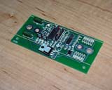
 Assembled clamper PCB. Making one or two is no problem.
 Try one hundred...
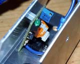
 PCB ready to be installed into the heat sink.
 Mounting PCB inside aluminum heat sink.
 Done. Top view.
 Side view.
 Overall view
 Real BMS plans and
clampers installation.
Real BMS plans and
clampers installation.
Development of a BMS module takes long
time, with main complexity being its software. The PCB with surface mount components was
designed to fit on top of 90Ah and 100Ah TS cells, and also inside the heat sink to
coexist with the voltage clamper. Having independent from BMS CPU voltage limiting
hardware (clamper) seem redundant, but actually is extra safety feature - in case the
software locks up (and watch dog unable to restart it) or any other BMS problem, the
clamper will always work backing it up. Currently BMS PCBs are not yet installed and heat
sink arrangement may change in future - I don't know for sure. But the current setup will
accommodate both PCBs nicely. Another challenge is to know what exactly the software
suppose to do. Today, even if all the BMS modules would be installed, the only function I
would implement for sure is displaying running condition (voltage and temperature) and ID
of each cell in real time and perhaps logging some charge-discharge history. Some data
have to be collected and understood to know for sure how to correct the charging to keep
the pack in balance - be it equal voltages, Ah balance, both or neither...
Below are the photos of real BMS installation concept which will be implemented in near
future. Today I only have clampers installed, and they do their job very nicely.
The BMS module PCB. PIC16F876
runs the show.
BMS module installed on the opposite side from the clamper PCB.
BMS module installed on top of 90Ah TS LiIon cell. This is one of options how it may to
look like.
Side view. The sink is installed onto a threaded posts screwed into the cell terminals.
Putting the posts into the terminals. Use only insulated tools. You don't
want to drop a wrench onto the posts...
After all the posts are installed, the cells are interconnected with
braided straps. Using the nuts with serrated flange helps keeping things tight.
Close up of the posts installed.
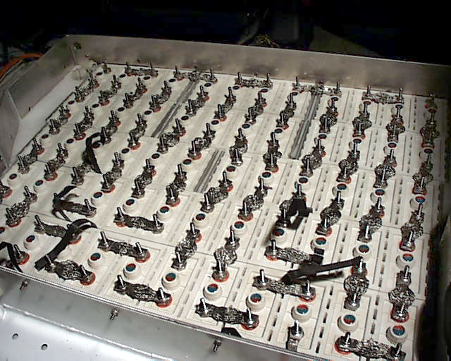
Large box ready for heat sinks.
Installing one by one. Of course there is sufficient gap between the
braided strap and the bottom of the sink!
The hole for negative post on each sink is insulated by the rubber grommet.
After installation the fuse connects the clamper.
It looks busy and lots of aluminum close together. I have to be careful.
 Finishing up.
At this point, it looks like slowing down
the charger is not even needed - 9.5A on charge gets distributed between full cells and
clampers such that the heat sinks aren't even warm. This is good news - no common bus
wiring really needed at this point and very clean installation - there are no connections
to any cell other than braided straps, and those are not even visible from the top. To
check functionality of all the clampers at once I've created special test charge profile -
3A charging current and no voltage limit (practically I set it to 450V, way above sum of
all the clamper voltages. If the pack is fully charged, this profile causes all the
clampers to go into regulation mode since they are the only devices setting voltage limit
per cell, so all LEDs should lit. Another benefit - I can adjust the clamping voltage at
the current the charger provides at the end of charge - I set 4.25V @ 3A. Actually IV
curve is so sharp, that it was not really necessary: at 4.23V there is no regulation, and
at 4.27V there is full blast 10A bypass - more than my charger outputs.
Finally after all adjustments covers were
made from transparent acrylic covering both boxes and laying on the heat sinks. This
allows safely open carpet lining and show off my creation. Later on aluminum covers will
be on top of acrylic sheets, holding cells in place even if the car is up side down. Hope
there won't be a need to test that...
Large box done - overview.
Small box done - overview.
The power cables enter the boxes through special insulating glands preventing axial
movement of the cable.
The main fuse and its retaining bracket.
The main fuse installed.
Another view angle of finished work.
Overall installation completed. Acrylic covers will protect the sinks from
top, and aluminum lids will cover the boxes as well.
Other view angle - large size photo.
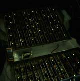
Testing functionality - special charging profile activates all the
clampers. Beautiful site!
Actual regulating. The cells reaching 4.25V limit first are well visible,
and bypassing allows others to catch up. Heat sinks are barely warm. All works as
designed.
