
...You can build a digital clock with its digits levitating in the air... |
 My small hobby project - mechanically scanned LED clock. It was built in 1998.
Red digits on this photo appear to float in the air in front of the clock.
This illusion is based on inertia of a human eye. If LED-formed digits will periodically
and frequently enough flash, they will appear solid and steady. And since the matrix of
digits is formed by a mechanically scanned single line of LEDs, and the fast rotating
clock body is not visible, it leaves digits "suspended" in the air. As far as I
know, the the first clock using this concept was built in 1997 by Bob Blick, so full credit for
the cool idea, original design and the software goes to Bob. Please visit his
page for yet more photos of his original clock and clocks built by other people.
My small hobby project - mechanically scanned LED clock. It was built in 1998.
Red digits on this photo appear to float in the air in front of the clock.
This illusion is based on inertia of a human eye. If LED-formed digits will periodically
and frequently enough flash, they will appear solid and steady. And since the matrix of
digits is formed by a mechanically scanned single line of LEDs, and the fast rotating
clock body is not visible, it leaves digits "suspended" in the air. As far as I
know, the the first clock using this concept was built in 1997 by Bob Blick, so full credit for
the cool idea, original design and the software goes to Bob. Please visit his
page for yet more photos of his original clock and clocks built by other people.
The heart of this clock is PIC16F84 microcontroller. (Older PIC16C84 version works just fine). The microcontroller is programmed with the code provided below.

First, mechanical stuff. We will use a 12V automotive fan (sells for $12.95) as a kit,
containing almost all nesessary mechanical parts. The only extra part you'll need is a
ball bearing and brass tube about 2mm in diameter. The bearing I've used was 22mm ext.
dia., 10mm int. dia., and 6mm high. This size is not very critical, (that's just what I
had in hand) but try to find something close: this one fits very nicely.

First you'll need to take the fan apart. The front grill and swing action mechanism parts
aren't needed. Don't throw away the propeller yet, you will use it's hub
later.

Next step is disassembling the motor. Slide the windings and commutator along the shaft
toward non-threaded end of the shaft leaving about 15mm of the shaft at this end. Be
careful not to separate the commutator from the rotor windings. The easiest way to do this
is to stick the commutator end of the shaft to the rear sleeve bearing (white plastic
part) and just tap the shaft with a hammer to the other end, using sleeve bearing as a
support. Once it's done, you'll need to solder a wire to the ends of three commutator
segments: 2 wires to any adjacent segments, and one wire to the segment opposite the other
two chosen previously.

Finished rotor should look like this. Of course, solder should not run over the surface of
the commutator segments where the brushes will touch them. Wrapping the commutator with a
stripe of paper (a few layers) before soldering, leaving only the ends exposed should
help.

Remove the small sleeve bearing from the plastic part. The larger bearing (left on this
picture) will take it's place. Just enlarge the hole with a "unibit" drill bit
to the diameter slightly less than bearing's external diameter to ensure a tight fit.

Take the small plastic gear from the fan's swinging mechanism and insert it into the ball
bearing tightly. You might need to file the gear a bit. Easiest way to do it is to put it
on the shaft, put the shaft in the chuck of an electric drill and use a file to grind off
some of the plastic. Once this plastic piece is inserted into the bearing, drill 3 tiny
holes (0.8mm to 1mm dia) for the wires to go through it's walls. Location of the holes
should roughly reflect position of the commutator segments to which the wires are
soldered. The whole assembly should look like the one in this photo.

Now it's time to assemble the motor. Run the three wires soldered to the commutator
through the respective holes and while holding the brushes in place, slide the assembly
along the long end of the shaft. As you go, make sure the wires aren't jammed between the
soldered points and white bearing insert. Then insert the rotor to the motor body and
tighten the two side screws.

Now the fun part: assembling the electronics. The electrical schematic of the clock is on
this picture. Right-click on it to enlarge the view. Bob Blick's original design is
slightly modified to accommodate voltage variations resulting from various rotating speeds
you may desire. Also, a small, cheap and light 3V lithium button cell replaces a
big, heavy and more expensive memory cap. This will help balance the clock. Some other
changes (in the rectifying and index pulse generating stages) were also made.

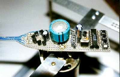
Place all the components on a piece of prototyping board, soldering components to the
plated-through holes. I highly recommend a socket for the PIC16F84 since you may want to
modify the code later to display seconds, blinking colon, or even having all clock display
analog "hands". Connect all the components soldering point to point with
wire-wrap wire. Hardware is so simple that it isn't really worth to make a PCB, but you
can certainly do that.

Once components are connected together, make the bar with LEDs. Solder cathodes of each
LED to the brass tube lining them up. Seven thin magnet wires running inside the
tube are used to connect the anodes to the circuit. Once the LEDs are in place, bend the
tube as shown here. Small posts (I've used 1N4401's leads for it) are soldered to the
bottom of the board (at each end) will hold the tube underneath the board. But before
securing tube under the board, place a plastic hub on it. The hub, as you might guess, is
center part of the propeller. Cut it out and drill the hole slightly smaller than diameter
of the brass tube. This will allow the tube to be moved back and forth for balancing the
rotating assembly.

Once the tube is in the hub (seven magnet wires should hang out at this point), solder the
tube to the prepared posts. Connect the seven wires to the board, ohming them first to
determine which is which. Put the hub on the rotor just as the propeller and secure it
with the spring. The last step is to connect the three wires supplying the power to
the board. The whole assembly will look like this.

You can bend the vertical part of the brass tube (where LEDs are) a little to the right as
they are facing you. This will create a slight tilt of all digits without disturbing the
balance.

The plastic motor housing will serve as the pedestal. I would suggest that you securely
hold the clock away from your face before turning on the power to the motor for the first
time since the unit probably will be out of balance. It is best to use a variable supply
and slowly increase the voltage. At 3-4 volts the clock won't work yet, but you can
balance the assembly by tilting and/or sliding it in the hub. After adjusting the clock's
balance, reset the controller: first cut off the motor power supply, then short pins
4 and 5 provided that the 3V cell is in place which keeps power to the circuit while the
motor supply is off. Then set the time and apply power to the motor.

Now if you'll supply at least 8.5V to the motor, you should see your clock running! If all
you see is smeared random characters, disconnect the power, short momentarily pins 4 and 5
of the PIC (which resets it), then set the time, and apply the power again (same as
above).
 If your clock displays
digits backwards, then it rotates clockwise. Simple reverse the polarity applied to the
motor.
If your clock displays
digits backwards, then it rotates clockwise. Simple reverse the polarity applied to the
motor.
You can download the original clock source code here, also
available on Bob's
page. The object code ready to be programmed into the PIC is here.
If you wish to have seconds displayed, grab the modified source code here.
The object code for this modification, ready to be programmed into the PIC, is here.
A code with seconds display yields this:

A few photos of another flavor of a similar clock with displaing seconds I built, are shown below. With bright LEDs and proper balancing the display will look sharp and cool, like on this photo (made in the dark). Good luck!


![]()
You can email me to: victor@metricmind.com