The adapter plate
Fabricated by SJ Precision
Material cost $130
Labor cost $350 (CAD data was provided to SJ precision)
 As the name implies,
the adapter plate "adapts" the motor mounting and centering means to those of
the clutch bell. The design must consider the mechanical strength requirements and the
distance between the motor flange and machined surface of the clutch bell. That in turn
depends on the shaft coupler length dictated by the shaft itself.
As the name implies,
the adapter plate "adapts" the motor mounting and centering means to those of
the clutch bell. The design must consider the mechanical strength requirements and the
distance between the motor flange and machined surface of the clutch bell. That in turn
depends on the shaft coupler length dictated by the shaft itself.
I designed the adapter plate myself since
it is part of the fun building an EV and is not really difficult. To do that you have to
know some dimensions on existing transmission and the motor. Triple check your
measurements and your math. Get good drafting software (CAD) allowing drawing in layers
and grouping objects. The best way to design the plate so that all the components are
match each other is to draw the cross section of the clutch assembly, the
motor flange, motor shaft and the coupler in actual size. I use Malz++Kassner CAD 4.7
Workstation for drafting mainly because it is very fast, accurate, allows using digitizer
and works with metric as well as English units. If you choose to make an adapter plate
yourself, below are the main steps as an example how I did it.
 Aluminum slab as sold by supplier to become an
adapter plate
Aluminum slab as sold by supplier to become an
adapter plate
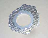
 The plate after milling, motor side. The visible serpentine pattern is the path of the
milling tool. Nice!
The plate after milling, motor side. The visible serpentine pattern is the path of the
milling tool. Nice!
 Other view angle
 Close up of the bolt head recess.
 Transmission side, note recesses made for the motor bolt heads
 The heads themselves had to be ground
off a bit not to interfere with the machined surface of the bell
The heads themselves had to be ground
off a bit not to interfere with the machined surface of the bell
 Do the bolt heads
stick out too much? No.
Do the bolt heads
stick out too much? No.
 All the bolts are inserted to verify alignment. Perfect!
 The plate placed on top of the transmission clutch bell.
 You will need to determine the distance between
them and between the center of each pin and the center of the transmission shaft. Unless
you have that data, start with accurate measurements using CNC equipment. The engine is
usually centered in the clutch bell with two dowel pins. +/-0.05mm measurement accuracy is
preferred; consider worse than +/-0.1 mm accuracy unacceptable. The shaft of the
transmission should not have side play, else replace it's pilot bearing.
You will need to determine the distance between
them and between the center of each pin and the center of the transmission shaft. Unless
you have that data, start with accurate measurements using CNC equipment. The engine is
usually centered in the clutch bell with two dowel pins. +/-0.05mm measurement accuracy is
preferred; consider worse than +/-0.1 mm accuracy unacceptable. The shaft of the
transmission should not have side play, else replace it's pilot bearing.
External contour of the plate should follow the contour of
the clutch bell except the places where the motor flange sticks outside the bell - in such
places the plate contour follows the motor flange. The contour accuracy of course is not
critical. My motor is quite large and its mounting holes overlap the bell machined surface
and its mounting holes. In return, the motor flange blocks access to the bolts tightening
the plate to the bell. Oh, well it will be fun assembling such a beast.
Once you determine all the mounting holes location, draw it
in CAD and print out in actual size. The fastest way to draw accurately enough the bell
shape is this: place flat sheet of drafting the paper on the transmission bell and press
against edges with your palm. When removed, the impression of the bell contour with all
the mounting and centering holes will be well visible. Outline it with black marker and
scan it in. If you don't have access to a large scanner there are two choices - best is to
draw a grid so when you cut the paper into smaller pieces which can fit on the scanner
bed, you can easily stitch back together pieces of the scanned images. In worst case, just
take a photo of the paper drawing with a digital camera and scale up resulting image
to the actual size. Do the same with the motor flange. It is easier to fix any mistakes on
the paper now than in the metal later. To determine mounting holes pattern a digital or
dial type calipers are sufficient; small misalignment here does not impact anything.
Once you drew all the transmission components, group the
lines representing each component to make it a separate object (like flywheel or coupler),
assign these objects to different layers to be able to move it around or hide it away to
reduce the clutter. "Move" (in CAD) the clutch assembly (flywheel and the
pressure plate) onto the tranny splined shaft. It should sit at the same place as in ICE
version. Then move coaxially the motor as close as you can to the clutch shaft, so
the shafts almost touch each other. If the distance between tranny flange and the motor
flange becomes less than 10 mm, don't move it any closer; the plate must have enough
mechanical strength. In my case I chose the gap between the shafts 0.5 mm. (If the
shaft has a threaded hole in its center for the bolt preventing the coupler from sliding
off, allow for the bolt head thickness). Then I just measured the resulted distance
between the motor flange and transmission flange which became the required thickness of
the adapter plate. Turn out to be 18.5 mm. Thick, but not bad. Now you can draw the shaft
coupler: since the the distance between the shafts is fixed, the length of the coupler is
pretty much predetermined too.
The CAD should allow grouping and
draw in layers, this greatly simplifies design.
You will need to measure distances A, B and C on CNC
table.
This is how all the components will mate together and how
the centering of the plate to the transmission plate is (usually) done.
Another view of the A, B, C measurement. Adapter plate
(green) and the motor flange (red) are overlaid.
Cross
sectionside view and front view of the drive train components
Since the motor has a round centering recess in its flange,
the plate must have respective centering ring sticking out for some height. For the
strength and integrity I didn't want to bolt separate centering ring to the plate; rather
machine it all from one solid piece of aluminum. Since I must use CNC mill anyway I can
mill this round ring on it as well, so no large lathe will be needed. The thickness of the initial plate material must
include the ring height. Recess on my motor flange is 10 mm deep, so for, say, 3 mm high
ring the total initial thickness of the aluminum slab must be at least 18.5+3=21.5mm. The
maximum thickness would be 18.5+10=28.5 mm. (The max of course can be more, that just
means I will waste aluminum by initially milling all the surface down to 28.5mm). Obvious
choice was standard 25.4 mm (1 inch) thick slab resulting in 25.4-18.5=6.9 mm high
centering ring. Cool.
Well, once the plate is drawn it can be machined. In my
case a few milling tools took care of everything: centering ring, drilled holes, recesses
for the bolt heads. You can see the serpentine trace of the end mill tool as it went
around and took off extra material. It is really fun to watch CNC equipment in action!
When the plate was ready I've tried to put respective bolts in it and see how well their
locations match the mounting holes in the flange. Not perfect, but it's OK since the only
function of the bolts is to keep the sandwich together; dowel pins placed with great
precision keep it all centered and prevent the shear movement.
If you wish to examine the drawing of my drive train in
CAD, download and install free viewer from the
original Malz++Kasha web site or its copy from my site. The drawing file is here (Shift+click to download).
The shaft coupler
Fabricated by American Machine and Gear
Material and labor cost $300
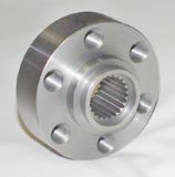 Another critical piece of the
drive train is the shaft coupler. This part is installed onto the shaft of the motor, in
my case it has machined splines inside matching the motor's splines. Once on the shaft it
is set against the ring on the shaft and held from sliding off by special bolt. The bolt
goes into the threaded center hole of the shaft. Since there is no axial force onto the
coupler other than the force created by the spinning mass when the vehicle turn (for the
cars with the motor across the body arrangement), this bolt does not have to be very
strong. Mine is machined of stainless steel with M6 thread. Special tool was made (out of
the large bolt head) to tighten this bolt and thread locking compound
("LockTite") was used on the thread as well as on the splines. After tightening
it becomes part of the motor shaft. Beautiful!
Another critical piece of the
drive train is the shaft coupler. This part is installed onto the shaft of the motor, in
my case it has machined splines inside matching the motor's splines. Once on the shaft it
is set against the ring on the shaft and held from sliding off by special bolt. The bolt
goes into the threaded center hole of the shaft. Since there is no axial force onto the
coupler other than the force created by the spinning mass when the vehicle turn (for the
cars with the motor across the body arrangement), this bolt does not have to be very
strong. Mine is machined of stainless steel with M6 thread. Special tool was made (out of
the large bolt head) to tighten this bolt and thread locking compound
("LockTite") was used on the thread as well as on the splines. After tightening
it becomes part of the motor shaft. Beautiful!
The shaft coupler. This
side is facing the motor flange.
The other side if the shaft coupler facing flywheel. Note recess made
for the special bolt.
Special bolt (thread M6) and the tightening tool made from a hex head
of the large bolt.
Coupler ready to be installed onto the motor shaft.
Done. Isn't it cool?
